# Three-dimensional solid continuum elements
text_image
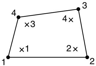
4 ×3 4×
×1 2×
1 2
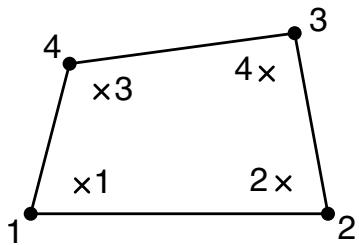
CIN3D8
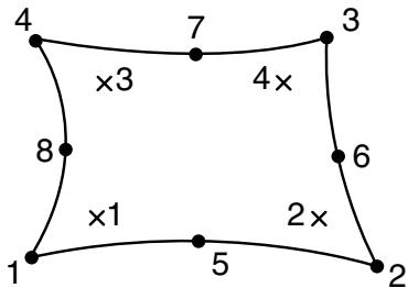
text_image
4
×3
7
4×
3
8
×1
1
5
2×
6
2
CIN3D12R
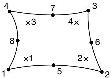
text_image
4
×3
7
4×
3
8
×1
1
5
2×
6
2
CIN3D18R
This shows the scheme in the layer closest to the 1–2–3–4 face. The integration points in the second layer are numbered consecutively.
# 28.4 Warping elements
• “Warping elements,” Section 28.4.1
• “Warping element library,” Section 28.4.2
# 28.4.1 WARPING ELEMENTS
Product: Abaqus/Standard
# References
• “Meshed beam cross-sections,” Section 10.6.1
• \*SOLID SECTION
# Overview
Warping elements:
• are used to model an arbitrarily shaped beam cross-section profile for use with Timoshenko beams;
• are used in conjunction with the beam section generation procedure described in “Meshed beam cross-sections,” Section 10.6.1; and
• model linear elastic behavior only.
# Typical applications
Warping elements are special-purpose elements that are used to discretize a two-dimensional model of a beam cross-section. This two-dimensional cross-section model is used in Abaqus/Standard to calculate the out-of-plane component of the warping function, as well as relevant sectional stiffness and mass properties that are required in a subsequent beam analysis in either Abaqus/Standard or Abaqus/Explicit. Applications include any structure whose overall behavior is beam-like, yet the cross-section is nonstandard or includes multiple materials. Examples include the cross-section of a ship for performing whipping analysis, a beam model of an airfoil-shaped rotor blade or wing, a laminated I-beam, etc.
# Choosing an appropriate element
To mesh an arbitrarily shaped solid beam cross-section Abaqus/Standard offers two elements: a 3-node linear triangle, WARP2D3, and a 4-node bilinear quadrilateral, WARP2D4. Adjacent elements in the cross-sectional mesh must share common nodes; mesh refinement using multi-point constraints is not allowed.
# Naming convention
Warping elements are named as follows:
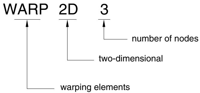
flowchart
```mermaid
graph TD
A["WARP"] --> B["2D"]
B --> C["3"]
C --> D["number of nodes"]
B --> E["two-dimensional"]
B --> F["warping elements"]
```
For example, WARP2D4 is 4-node warping element in two dimensions.
# Defining the element’s section properties
You use a solid section definition to define the section properties. You must associate these properties with a region of your model. No additional data are necessary.
Input File Usage: \*SOLID SECTION, ELSET=name
where the ELSET parameter refers to a set of warping elements.
# Assigning a material definition to a set of warping elements
You must associate a linear elastic material definition with each warping element section definition. Optionally, you can associate a material orientation definition with the section (see “Orientations,” Section 2.2.5).
Only isotropic linear elasticity (“Defining isotropic elasticity” in “Linear elastic behavior,” Section 22.2.1) or orthotropic linear elasticity for warping elements (“Defining orthotropic elasticity for warping elements” in “Linear elastic behavior,” Section 22.2.1) are valid material models for warping elements.
Input File Usage: \*SOLID SECTION, ELSET=name, MATERIAL=name, ORIENTATION=name
# 28.4.2 WARPING ELEMENT LIBRARY
Product: Abaqus/Standard
# References
• “Meshed beam cross-sections,” Section 10.6.1
• \*SOLID SECTION
# Overview
This section provides a reference to the warping elements available in Abaqus/Standard.
# Element types
WARP2D3 3-node linear two-dimensional warping element WARP2D4 4-node bilinear two-dimensional warping element
Active degree of freedom
3, representing the out-of-plane warping function
Additional solution variables
None.
# Nodal coordinates required
X, Y
# Element property definition
Input File Usage: \*SOLID SECTION
# Element-based loading
There is no loading for these element types.
# Element output
No output is available for these element types. The two-dimensional warping elements are used to calculate the out-of-plane warping function for beams using a meshed cross-section. This warping function can be viewed in the Visualization module of Abaqus/CAE. The derivatives of the warping function are used to calculate the shear strain and stress at the integration points of the elements due to torsion.
# Node ordering on elements
text_image
Y
X
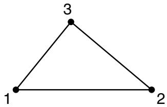
text_image
1
2
3
3 - node element
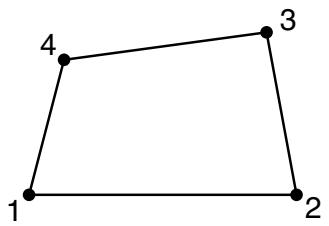
text_image
1
2
3
4
4 - node element
# Numbering of integration points for output
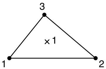
text_image
3
× 1
1
2
3 - node element
text_image
4
×3
4×
×1
2×
1
2
3
4 - node element
# 29. Structural Elements
Membrane elements 29.1
Truss elements 29.2
Beam elements 29.3
Frame elements 29.4
Elbow elements 29.5
Shell elements 29.6