# 32.10.2 ELASTIC-PLASTIC JOINT ELEMENT LIBRARY Product: Abaqus/Aqua # References • “Elastic-plastic joints,” Section 32.10.1 • \*EPJOINT # Overview This section provides a reference to the elastic-plastic joint elements available in Abaqus/Aqua. # Element types JOINT2D Two-dimensional elastic-plastic joint element JOINT3D Three-dimensional elastic-plastic joint element Active degrees of freedom 1, 2, 6 for JOINT2D 1, 2, 3, 4, 5, 6 for JOINT3D Additional solution variables None. # Nodal coordinates required # Element property definition Input File Usage: \*EPJOINT # Element-based loading None. # Element output The relative displacements and rotations corresponding to the forces and moments below are chosen by requesting the corresponding “strains.” Elastic and plastic strains are available. For a spud can the vertical (plastic) embedment since the start of the analysis is given by PE11; the total vertical embedment is available as PEEQ. JOINT2D
S11Total direct force in the first local direction.
S22Total direct force in the second local direction.
S12Total moment about the third local direction.
JOINT3D
S11Total direct force in the first local direction.
S22Total direct force in the second local direction.
S33Total direct force in the third local direction.
S12Total moment about the third local direction.
S13Total moment about the second local direction.
S23Total moment about the first local direction.
# Nodes associated with the element Two nodes. # 32.11 Drag chain elements • “Drag chains,” Section 32.11.1 • “Drag chain element library,” Section 32.11.2 # 32.11.1 DRAG CHAINS Product: Abaqus/Standard # References • “Drag chain element library,” Section 32.11.2 • \*DRAG CHAIN • \*RIGID SURFACE # Overview Drag chain elements: • are used for simulating the effects of drag chains on the seabed for near bottom bending simulation modeling; and • can be used in two-dimensional or three-dimensional problems. # Typical applications 
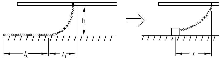
The drag chain is modeled as a concentrated weight on the seabed, with a chain between it and an attachment point on the pipe (see Figure 32.11.1–1). ![](images/page-1045_befd7af7256de5d6d5623f1b45b8def7efdbea9185ebd2f8e1fbf9dd53df003d.jpg)
text_image h l₀ l₁ → l
Figure 32.11.1–1 Drag chain model. Given a uniform drag chain of total length $\ell _ { c } ,$ , weight per unit length $w ,$ and friction coefficient $\mu$ between it and the seabed, attached to the pipeline at height h above the seabed, the length of chain on the seabed at slip, $\ell _ { 0 }$ , is given by $$ \ell_ {0} = \ell_ {c} \left[ 1 + \frac {\mu h}{\ell_ {c}} - \left\{\left(1 + \frac {\mu h}{\ell_ {c}}\right) ^ {2} - 1 + \left(\frac {h}{\ell_ {c}}\right) ^ {2} \right\} ^ {1 / 2} \right] $$ and the horizontal projection of the suspended length, $\ell _ { 1 } { \mathrm { : } }$ , is $$ \ell_ {1} = \sqrt {2 \mu h \ell_ {0}}. $$ Thus, the equivalent model should have a friction limit of $\dot { } \mu w \ell _ { 0 }$ The horizontal length at slip, , can be taken as any value from $\ell _ { 1 }$ to $\ell _ { 1 } + \ell _ { 0 }$ . Comparison with experiment has shown that taking this length as $\ell = \ell _ { 1 } + \ell _ { 0 } / 2$ is a reasonable choice. When the pipeline attachment point is directly above the weight, there will be no horizontal force or horizontal stiffness offered by a drag chain element; this position is assumed as the initial condition. As the pipe moves relative to the seabed, the horizontal force on the pipeline caused by the drag chain opposes the relative motion and gradually increases (an approximation to the catenary equation is used to relate the force to the offset ) until the drag chain slips when the force reaches the friction limit. The height, $h ,$ is assumed to be small compared to $\mu \ell _ { 0 }$ . # Choosing an appropriate element Two- and three-dimensional drag chain elements are available. Element DRAG2D assumes that the seabed is flat and parallel to the plane in which the pipe is moving; therefore, the seabed does not have to be modeled explicitly. Element DRAG3D requires that the seabed be defined as an analytical rigid surface, which must be flat and parallel to the global (X, Y) plane and is considered to be fixed throughout the analysis. # Defining the seabed for three-dimensional drag chains The seabed is defined as an analytical rigid surface. This surface definition is used to determine if the chain touches the seabed, depending on the separation between the pipe node and the position of the seabed surface. See “Analytical rigid surface definition,” Section 2.3.4, for more information. Since the seabed is considered to be fixed, boundary conditions must be applied to the rigid body reference node of the seabed surface, which is also the second node of the DRAG3D element. Input File Usage: Use the following option to define the seabed surface for DRAG3D elements: \*RIGID SURFACE In a model defined in terms of an assembly of part instances, the rigid surface definition that defines the seabed must appear inside the same part definition as the drag chain elements. # Defining the drag chain behavior For DRAG2D elements you specify the maximum horizontal length, , between the attachment point and the concentrated weight. At this length the weight will start to slip on the seabed. In addition, you specify the horizontal force between the weight and the seabed at slip (that is, the frictional limit). For DRAG3D elements you specify the total length of the chain, the friction coefficient, and the weight per unit length of chain. You must associate the drag chain behavior with a set of drag chain elements. Input File Usage: \*DRAG CHAIN, ELSET=name drag chain data # 32.11.2 DRAG CHAIN ELEMENT LIBRARY Product: Abaqus/Standard # References • “Drag chains,” Section 32.11.1 • \*DRAG CHAIN • \*RIGID SURFACE # Overview This section provides a reference to the drag chain elements available in Abaqus/Standard. # Element types DRAG2D Two-dimensional drag chain, for use in cases where only horizontal motion is being studied DRAG3D Three-dimensional drag chain Active degrees of freedom DRAG2D: 1, 2 DRAG3D: At the first node: 1, 2, 3. At the second node: 1, 2, 3, 4, 5, 6. Additional solution variables None. # Nodal coordinates required DRAG2D: (X, Y) coordinates of the pipeline attachment node in the horizontal plane. DRAG3D: (X, Y, Z) coordinates of both nodes. # Element property definition Input File Usage: Use the following option to define the horizontal length at slip and the friction limit: \*DRAG CHAIN Use the following option to define the seabed for DRAG3D elements: \*RIGID SURFACE The rigid surface must be flat and parallel to the global (X, Y) plane. # Element-based loading None. Element output
S11The horizontal component of force supported by the drag chain in the plane parallel to the seabed.
S12The vertical component of force in the drag chain for DRAG3D elements.
E11The horizontal length of the drag chain for DRAG2D elements. The length of chain on the seabed floor (not suspended) for DRAG3D elements.
E12The orientation of the drag chain (angle from the global X-axis).
# Nodes associated with the element DRAG2D: One node at the position where the chain attaches to the pipe. DRAG3D: Two nodes. The first node is the node where the chain attaches to the pipe; the second node is the “reference node” of the rigid body containing the rigid surface that defines the seabed. # 32.12 Pipe-soil elements • “Pipe-soil interaction elements,” Section 32.12.1 • “Pipe-soil interaction element library,” Section 32.12.2