다축의 집중차륜하중이 한 조로 재하될 때 해석작업의 효율성을 고려하여 midasCivil에서 사용할 수 있는 재하방법은 다음과 같습니다
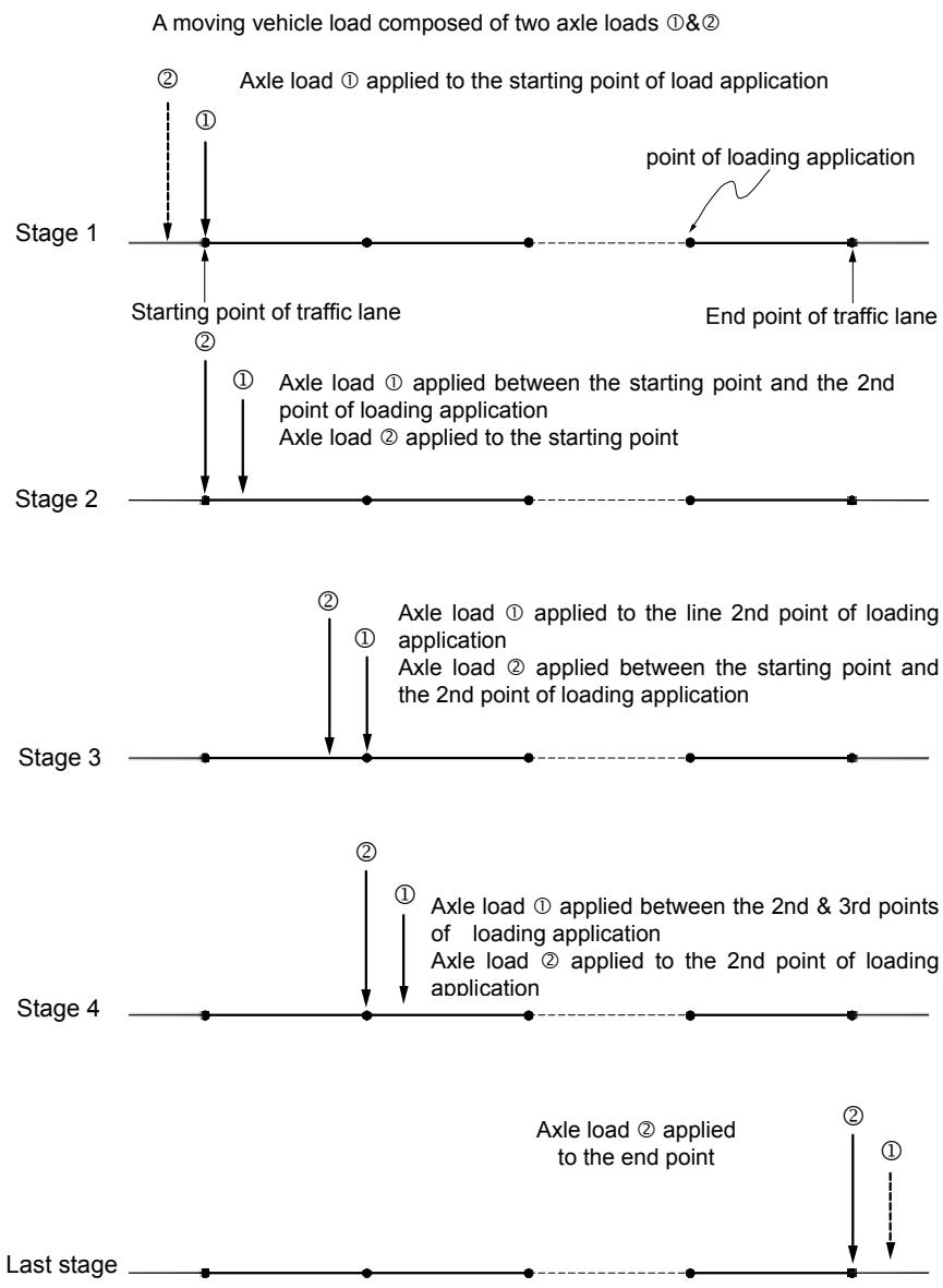
1. 이 방법은 다축 집중차륜하중을 구성하고 있는 개개의 집중하중을 순차적으로 차선을 따라 이동하면서 매 하중작용점에 재하하게 되고, 다축의 집중차륜하중 중의 나머지 집중하중이 하중작용점 사이에 위치할 경우에는인접한 두 개의 하중작용점에서의 영향선(또는 영향면) 값을 보간하여 계산하는 방법입니다. 따라서 이 방법은 주어진 영향선(또는 영향면)의 정확도 범위 내에서 정확한 설계치를 산출합니다. 그러나 이 방법은 차선을 따라가면서 모든 하중작용점에 재하하기 때문에 해석소요시간이 길어지는 단점이 있습니다. 사용자지침서에서는 이 방법을 ‘E’(Exact)라고 약칭합니다. (그림 2.13.15 참조)
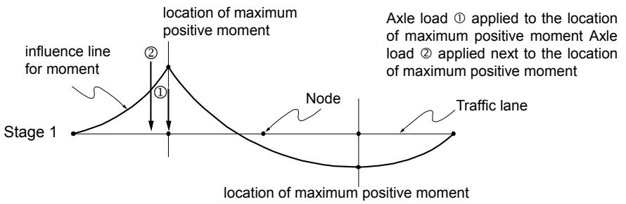
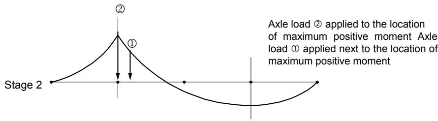
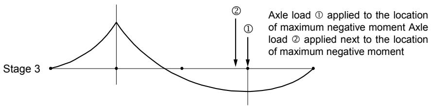
2. 방법 1에서는 개개의 집중하중을 차선을 따라 이동하면서 매 작용점에 재하하는 반면, 이 방법은 영향선(또는 영향면) 내에서 최대최소 설계변수가발생한 위치에만 재하시키게 되며 나머지는 방법 1과 같습니다. 사용자지침서에서는 이 방법을 ‘Q’(Quick)라고 약칭합니다. (그림 2.13.16 참조)
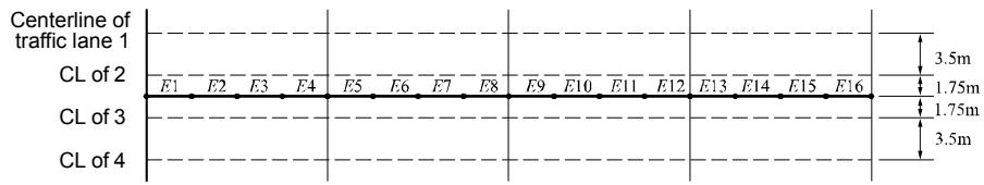
3. 방법 1에서는 다축 집중차륜하중을 구성하고 있는 개개의 집중하중을 순차적으로 매번 차선을 따라 이동재하하는 반면, 이 방법에서는 1개의 기준차축을 선정하여 매 하중작용점에 재하하고 나머지 차축에 의한 영향은 보간한 값을 사용합니다. 여기서 기준차축은 차량무게중심에서 가장 가까운 위치에 있는 차축으로 midas Civil 내부에서 자동 설정됩니다. 사용자지침서에서는 이 방법을 ‘P’(Pivot)라고 약칭합니다. (그림 2.13.17 참조)
상기 재하방법중 예비설계 단계에서는 방법 2를 이용하고, 방법 1 또는 3은 최종설계 단계에서 사용하는 것이 효과적입니다.
또한, 2개 이상의 집중차륜하중이 한 조로 재하될 때, 앞뒤의 하중값 또는 차축간격이 서로 상이해서 비대칭으로 재하될 경우에는 차량의 주행방향에 따라 차량하중이 미치는 영향이 다르기 때문에 양방향 주행효과를 고려하여 차선요소에 재하됩니다.
flowchart
```mermaid
graph TD
A["A moving vehicle load composed of two axle loads ①&②"] --> B["Stage 1"]
B --> C["Starting point of traffic lane"]
C --> D["Stage 2"]
D --> E["Stage 3"]
E --> F["Stage 4"]
F --> G["Last stage"]
B --> H["Point ①: Axle load ① applied to the starting point of load application"]
B --> I["Point ②: Axle load ② applied to the starting point"]
D --> J["Point ①: Axle load ① applied between the starting point and the 2nd point of loading application"]
D --> K["Point ②: Axle load ② applied between the starting point and the 2nd point of loading application"]
E --> L["Point ①: Axle load ① applied to the line 2nd point of loading application"]
E --> M["Point ②: Axle load ② applied between the starting point and the 2nd point of loading application"]
F --> N["Point ①: Axle load ① applied between the 2nd & 3rd points of loading application"]
F --> O["Point ②: Axle load ② applied to the 2nd point of loading application"]
G --> P["Point ①: Axle load ② applied to the end point"]
G --> Q["Point ②: Axle load ② applied to the end point"]
```
그림 2.13.15 ‘E’(Exact) 방법에 따른 집중차륜하중의 재하개념
A moving vehicle load composed of two axle loads &
flowchart
```mermaid
graph TD
A["Stage 1"] --> B["influence line for moment"]
B --> C["Location of maximum positive moment"]
C --> D["Node"]
D --> E["Location of maximum positive moment"]
E --> F["Traffic lane"]
C --> G["Axle load ① applied to the location of maximum positive moment"]
C --> H["Axle load ② applied next to the location of maximum positive moment"]
```
text_image
Stage 2
②
①
Axle load ② applied to the location
of maximum positive moment Axle
load ① applied next to the location of
maximum positive moment
text_image
Stage 3
①
②
① applied to the location
of maximum negative moment Axle load
② applied next to the location
of maximum negative moment
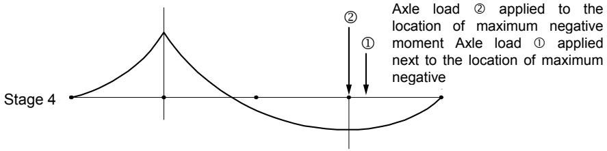
text_image
Stage 4
①
②
① applied to the
location of maximum negative
moment Axle load ① applied
next to the location of maximum
negative
그림 2.13.16 ‘Q’(Quick) 방법에 따른 집중차륜하중의 재하개념
A moving vehicle load composed of two axle loads & if axle load is reference axle
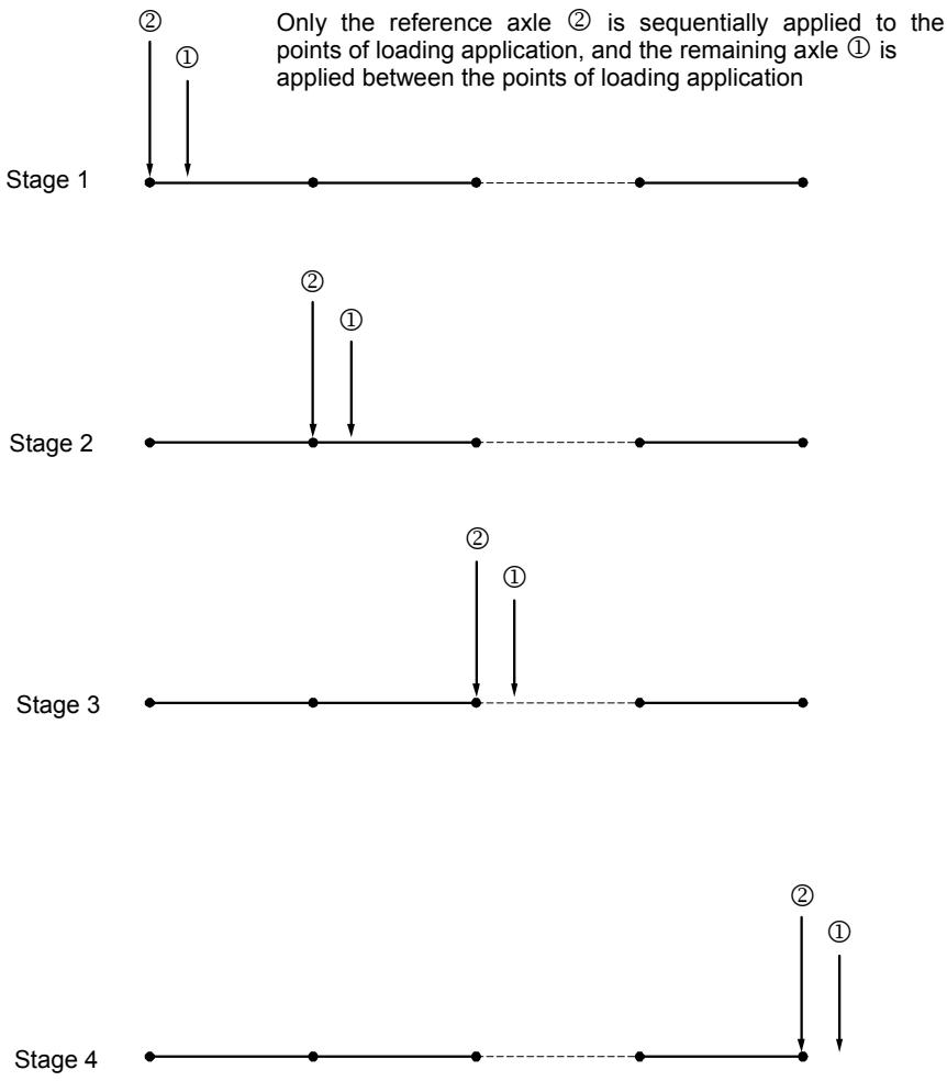
그림 2.13.17 ‘P’(Pivot ) 방법에 따른 집중차륜하중의 재하개념
# 13-3 차량하중의 재하조건
교량구조물의 해석시 가장 불리한 조건의 설계변수(부재내력, 변위, 지지점반력 등)를 도출하기 위해서는 모든 차량이동하중 재하조건이 고려되어야 합니다. 즉, 설계차량하중의 그룹과 차선수가 여러 개일 경우, 고려해야할 설계차량하중이 동시에 재하되어야 하는 것인지, 아니면 여러 설계차량하중 그룹 중에서 가장 불리한 조건의 차량하중만 고려되어야 하는지, 그리고 동시에 재하가능한 임의의 차량하중이 여러 차선중 특정 차선에만 재하되는 것인지, 또한 여러 차선에 차량하중을 동시에 재하할 경우 감소율은 동시 재하차선수에 따라 얼마나 적용할 것인지 등 설계변수에 영향을 미치는 모든 조건을 고려하여야 합니다.
midas Civil는 이와 같은 설계조건을 고려하여 순열조합방법을 통해 모든 발생가능한 조건에 대한 최대최소 설계변수를 산출합니다.
midas Civil에서 최대최소 설계변수를 산출하는데 필요한 데이터는 다음과 같습니다.
■ 설계차량하중 그룹과 재하할 차선번호
▪ 동시에 재하할 수 있는 최소최대차선수
▪ 동시에 재하할 차선수에 따른 차량하중 감소율
- Permit Load 인 경우에는 특성에 맞는 입력방법 사용
line
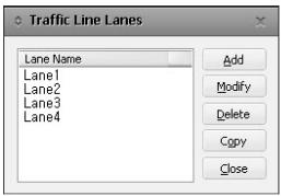
| CL Section | Distance (m) |
| ---------- | ------------ |
| E1 | 3.5 |
| E2 | 1.75 |
| E3 | 1.75 |
| E4 | 1.75 |
| E5 | 1.75 |
| E6 | 1.75 |
| E7 | 1.75 |
| E8 | 1.75 |
| E9 | 1.75 |
| E10 | 1.75 |
| E11 | 1.75 |
| E12 | 1.75 |
| E13 | 1.75 |
| E14 | 1.75 |
| E15 | 1.75 |
| E16 | 1.75 |
| CL of 2 | 3.5 |
| CL of 3 | 3.5 |
| CL of 4 | 3.5 |
(a) 평면도

(b) 입면도
그림 2.13.18 구조물 모델
다음은 midas Civil에서 이동하중 순열조합에 대한 개념을 설명하기 위한 예입니다.
[ 예제1 ] 한국도로교설계기준의 DB-24, DL-24 하중조건을 고려하여 4개 차선을가진 구조물의 해석
# 1. 이동하중으로 “한국도로교설계기준 을 선택합니다.
Main Menu에서 Load탭>Load Type그룹>Moving Load>Moving LoadCode>Korea를 선택합니다.
# 2. 차선을 입력합니다.
Moving Load Analysis Data그룹>Traffic Line Lanes을 선택하면 아래와 같이 Traffic Line Lanes의 입력상황을 보여주는 대화상자가 활성화됩니다.새로운 차선을 정의하기 위해선 아래 그림과 같은 차선입력 대화상자를 호출합니다. Lane Name에 차선 이름을 입력하고, 차선을 이루는 일련의 보요소를 선택한 후 편심거리(Eccentricity)와 충격계수를 입력하여 차선을 정의합니다.
text_image
Traffic Line Lanes
Lane Name
Lane1
Lane2
Lane3
Lane4
Add
Modify
Delete
Copy
Close
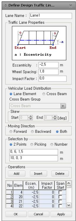
text_image
Define Design Traffic Lin...
Lane Name : Lane1
Traffic Lane Properties
Start End
a : Eccentricity
Eccentricity : -2,5 m
Wheel Spacing: 1,8 m
Impact Factor : 0,0
Vehicular Load Distribution
Lane Element Cross Beam
Cross Beam Group
Cross Beam
Skew
Start End 0 [deg]
Moving Direction
Forward Backward Both
Selection by
2 Points Picking Number
0, 6, 1,5 m
10, 0, 3 m
Operations
Add Insert Delete
No Elem Eccen, Impact Span
(m) Factor Start
1 4 -2,5 0
2 20 -2,5 0
3 21 -2,5 0
4 22 -2,5 0
OK Cancel Apply
차선입력 대화상자
# 3. 차량하중을 입력합니다.
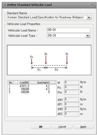
Moving Load Analysis Data그룹>Vehicles의 Add Standard에서 원하는 기준을 선택한 후(여기에서는 Korean Standard Load), 원하는 하중을 선택하여입력합니다.
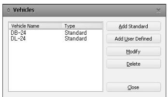
text_image
Vehicles
Vehicle Name Type
DB-24 Standard
DL-24 Standard
Add Standard
Add User Defined
Modify
Delete
Close
text_image
Define Standard Vehicular Load
Standard Name
Korean Standard Load(Specification for Roadway Bridges)
Vehicular Load Properties
Vehicular Load Name : DB-24
Vehicular Load Type : DB-24
P1 P2 P3
D1 D2
No Load(N) Spacing(m)
1 47071.9 4.2
2 188288 4.2
3 188288 9
W 0 N/m
Ps 0 N
Pm 0 N
dW1 0 N/m
dD1 0 m
dW2 0 N/m
dD2 0 m
OK Cancel Apply
차량하중의 정의
DB-24와 DL-24 중에서 불리한 조건을 고려하기 위해 다음 그림과 같이 동일한 차량하중그룹(Class 1)을 사용합니다.
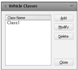
text_image
Vehicle Classes
Class Name
Class1
Add
Modify
Delete
Close
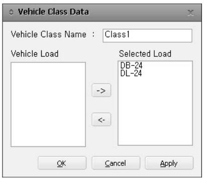
text_image
Vehicle Class Data
Vehicle Class Name : Class1
Vehicle Load
Selected Load
DB-24
DL-24
OK Cancel Apply
차량하중그룹입력
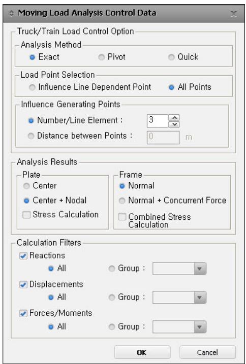
# 4. 차량하중의 재하방법을 입력합니다.
Main Menu의 Analysis탭>Analysis Control그룹>Moving Load AnalysisControl 에서 그림과 같이 ‘Exact’을 선택하고 차량하중의 재하방법을지정합니다.
text_image
Moving Load Analysis Control Data
Truck/Train Load Control Option
Analysis Method
● Exact
● Pivot
● Quick
Load Point Selection
● Influence Line Dependent Point
● All Points
Influence Generating Points
● Number/Line Element : 3
● Distance between Points : 0 m
Analysis Results
Plate
● Center
● Center + Nodal
□ Stress Calculation
Frame
● Normal
● Normal + Concurrent Force
□ Combined Stress
Calculation Filters
● Reactions
● All
● Group :
● Displacements
● All
● Group :
● Forces/Moments
● All
● Group :
OK Cancel
차량하중의 재하방법
5. 차량하중이 동시에 재하되는 차선수에 대한 차량하중 감소율을 입력합니다.아래 그림과 같이 동시에 재하되는 차선수가 1에서 4까지 변할 때의 차량하중감소율을 입력합니다.
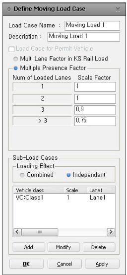
text_image
Define Moving Load Case
Load Case Name : Moving Load 1
Description : Moving Load 1
Load Case for Permit Vehicle
Multi Lane Factor in KS Rail Load
Multiple Presence Factor
Num of Loaded Lanes Scale Factor
1 1
2 1
3 0,9
> 3 0,75
Sub-Load Cases
Loading Effect
Combined Independent
Vehicle class Scale Lane1
VC:Class1 1 Lane1
Add Modify Delete
OK Cancel Apply
차량하중이 동시에 재하되는 차선수에 대한 차량하중 감소율
다음과 같이 차량하중그룹, 재하될 차선, 재하되는 최대ㆍ최소 차선 수를사용하여 차량하중 재하조건을 입력합니다
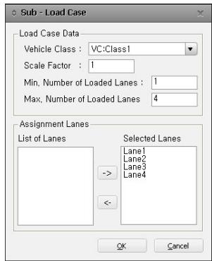
text_image
Sub - Load Case
Load Case Data
Vehicle Class : VC:Class1
Scale Factor : 1
Min. Number of Loaded Lanes : 1
Max. Number of Loaded Lanes : 4
Assignment Lanes
List of Lanes
Selected Lanes
Lane1
Lane2
Lane3
Lane4
->
<-
OK Cancel
차량하중그룹과 차선을 사용한 차량하중 재하조건의 입력
이상의 입력된 조건에 따라 midas Civil에서 자동으로 순열 조합되는 조건의 개수는 아래의 표와 같이 15가지가 되고, 최대 최소설계변수는 이 15가지 조건에 대해 가장 불리한 값으로 각각 산출됩니다
“DB-24 or DL-24”는 두가지 차량하중조건에 대해불리한 최대•최소 설계변수를 산출한다는 의미이다.
| 순열조합조건번호 | 재하될 차선번호 | 차량하중감소율 |
| #1 | #2 | #3 | #4 |
| 1 | DB-24 or DL-24 | | | | 1.0 |
| 2 | | DB-24 or DL-24 | | | 1.0 |
| 3 | | | DB-24 or DL-24 | | 1.0 |
| 4 | | | | DB-24 or DL-24 | 1.0 |
| 5 | DB-24 or DL-24 | DB-24 or DL-24 | | | 1.0 |
| 6 | DB24 or DL-24 | | DB-24 or DL-24 | | 1.0 |
| 7 | DB-24 or DL-24 | | | DB-24 or DL-24 | 1.0 |
| 8 | | DB-24 or DL-24 | DB-24 or DL-24 | | 1.0 |
| 9 | | DB-24 or DL-24 | | DB-24 or DL-24 | 1.0 |
| 10 | | | DB-24 or DL-24 | DB-24 or DL-24 | 1.0 |
| 11 | DB-24 or DL-24 | DB-24 or DL-24 | DB-24 or DL-24 | | 0.9 |
| 12 | DB-24 or DL-24 | DB-24 or DL-24 | | DB-24 or DL-24 | 0.9 |
| 13 | DB-24 or DL-24 | | DB-24 or DL-24 | DB-24 or DL-24 | 0.9 |
| 14 | | DB-24 or DL-24 | DB-24 or DL-24 | DB-24 or DL-24 | 0.9 |
| 15 | DB-24 or DL-24 | DB-24 or DL-24 | DB-24 or DL-24 | DB-24 or DL-24 | 0.75 |