Clearly this procedure can be extended to deal with a stiffener that is arbitrarily oriented in space, and with rigid links that are not perpendicular to the stiffener.
The foregoing transformation introduces an error that can cause displacements to be significantly overestimated [7.1]. The error can be attributed to incomplete coupling between beam and plate. Axial displacement in the beam should be
$$
u _ {\text { beam }} = u _ {\text { plate }} + b \theta_ {\text { plate }} \tag {7.8-3}
$$
Imagine, for example, that all d.o.f. of the plate in Fig. 7.8-1b are zero but $w_{2}$ . Then $w_{plate}$ is cubic in x and $\theta_{plate}$ is quadratic in x. Hence, according to Eq. 7.8-3, $u_{beam}$ should be quadratic in x. However, Eq. 7.8-1 yields $u_{3} = u_{4} = 0$ ; hence, $u_{beam} = 0$ . Thus, for this deformation mode, beam and plate bending stiffnesses are simply added rather than being combined in a way that recognizes a common neutral axis. For a test case in which a uniform cantilever was loaded by a transverse tip force, with n plate elements along the length, tip displacement was overestimated by 69% for n = 1, 17% for n = 2, and 4.3% for n = 4 [7.1]. The error tends toward zero as each element approaches a state of constant curvature.
A method that eliminates the error was suggested by Miller [7.2]. He introduces axial displacement d.o.f. at x = L/2, say $u_{5}$ in the plate and $u_{6}$ in the beam. Axial displacement in the beam is now quadratic in x, as is desired. The axial stiffness portion of $[k']$ is 3 by 3 and is associated with $u_{3}$ , $u_{4}$ , and $u_{6}$ (see Section 6.2). The transformation is essentially that of Eq. 7.8-2, augmented by
$$
u _ {6} = u _ {5} + b \left(\frac {d w}{d x}\right) _ {x = L / 2} \tag {7.8-4}
$$
where plate rotation $dw/dx$ depends on $w_1$ , $\theta_1$ , $w_2$ , and $\theta_2$ . Transformation causes the 7 by 7 beam element stiffness matrix to operate on d.o.f. $u_1$ , $w_1$ , $\theta_1$ , $u_2$ , $w_2$ , $\theta_2$ , and $u_5$ . This matrix is then combined with the plate element stiffness matrix (whose row and column corresponding to $u_5$ are null). Finally, condensation removes $u_5$ , thus producing a combined [k] that operates on the usual plate element d.o.f.
Another difficulty, encountered in dynamic problems, is that the transformation converts a diagonal beam mass matrix $[m']$ to a nondiagonal mass matrix [m]. Ad hoc adjustments of [m] can make it diagonal again.
Rigid Elements. A rigid element might be used to model part of a linkage mechanism that couples elastic bodies. Or a particular element might be of much higher modulus than surrounding elements. In the latter case, errors of the type discussed in Section 18.2 are likely, and it is better to make the element perfectly rigid rather than very stiff.
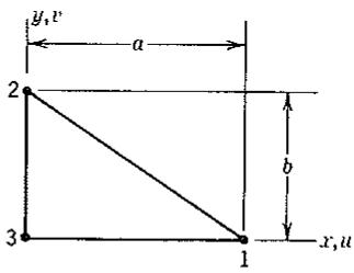
Imagine that the triangle of Fig. 7.8-2 is to be idealized as perfectly rigid.
text_image
y,v
a
2
b
3
1
x,u
Figure 7.8-2. A plane triangle. Other elements of the structure are connected to it but are not shown.
Therefore, its motion is completely described by three d.o.f., say $u_1, v_1$ , and $u_2$ . These d.o.f.-are related to the original six d.o.f. by the transformation
$$
\{\mathbf {d} ^ {\prime} \} = [ \mathrm{T} ] \{\mathbf {d} \} \quad \text { or } \quad \left\{ \begin{array}{l} u _ {1} \\ v _ {1} \\ u _ {2} \\ v _ {2} \\ u _ {3} \\ v _ {3} \end{array} \right\} = \left[ \begin{array}{c c c} 1 & 0 & 0 \\ 0 & 1 & 0 \\ 0 & 0 & 1 \\ - a / b & 1 & a / b \\ 1 & 0 & 0 \\ - a / b & 1 & a / b \end{array} \right] \left\{ \begin{array}{l} u _ {1} \\ v _ {1} \\ u _ {2} \end{array} \right\} \tag {7.8-5}
$$
in which $u_{3} = u_{1}$ and $v_{2} = v_{3} = v_{1} - \theta a$ , where $\theta = (u_{1} - u_{2}) / b$ is a small rigid-body rotation. Transformation according to Eq. 7.8-5 is applied to all elements of the structure that contain any of the d.o.f. $v_{2}, u_{3}$ , and $v_{3}$ . Thus, $v_{2}, u_{3}$ , and $v_{3}$ no longer appear as d.o.f. in $\{\mathbf{D}\}$ . The particular stiffness coefficients of triangle 1-2-3 do not matter; they are overridden by the rigid-body constraint.
The choice $\{\mathbf{d}\} = [u_1 - v_1 - u_2]^T$ is not unique, and would be unacceptable if node numbers were rearranged so that $y_2 - y_1 = b = 0$ . Not only would there be a division by zero in Eq. 7.8-5, but the use of $u_1$ and $u_2$ as independent d.o.f. would contradict the assumption that the triangle is rigid.
# PROBLEMS
# Section 7.2
7.1 If a vector $\mathbf{V}$ has length $L$ , then $\mathbf{V} \cdot \mathbf{V} = L^2$ regardless of the coordinate system in which $\mathbf{V}$ resides. Hence, using Eq. 7.2-1, show that $\Sigma \ell_i = 1$ , $\Sigma \ell_i m_i = 0$ , and so on (six such relations altogether).
7.2 (a) Let $x' = -x$ and $y' = -y$ . What is [A] in Eq. 7.2-1 if both coordinate systems are right-handed?
(b) Similarly, what is $[\Lambda]$ if $x' = y$ and $z' = z$ ?
7.3 (a) If $z = z'$ and $x'$ is located at a counterclockwise angle $\theta$ from $x$ , what is [A] in Eq. 7.2-1?
(b) For this $[\Lambda]$ , show that $[\Lambda]^{-1} = [\Lambda]^T$ .
# Section 7.3
7.4 Let $[\mathbf{E}']$ be 3 by 3, as for a plane stress problem. Show that Eq. 7.3-10 yields $[\mathbf{E}'] = [\mathbf{E}]$ if the material is isotropic.
7.5 Let an orthotropic material have principal directions $x', y'$ , and $z$ (i.e., axes $z'$ and $z$ coincide). Write the 6 by 6 matrix $[T_{\epsilon}]$ for this situation. Express your answer in terms of $\sin \beta$ and $\cos \beta$ .
7.6 Consider a plane problem for which the 3 by 3 matrix $[\mathbf{E}']$ is diagonal, with $E_{11}' = E_a$ , $E_{22}' = E_b$ , and $E_{33}' = G$ . What is [E] for an arbitrary angle $\beta$ in Fig. 7.3-1? As a partial check on your answer, try the case $\beta = \pi/2$ .
7.7 Is $[\mathbf{T}_{\epsilon}]$ of Eq. 7.3-11 an orthogonal matrix?
# Section 7.4
7.8 For a given distortion, strain energy in an element (Eq. 4.1-10) must be independent of the coordinate system in which it is computed. Use this argument to derive Eq. 7.4-4.
# Section 7.5
7.9 Two forms of $[k']$ for a truss element are given in Section 7.5, one by Eq. 7.5-1 and the other by Eq. 7.5-2. Verify that appropriate transformation of each form produces the stiffness matrix of Eq. 2.4-3.
7.10 (a) Verify the [k] determined in Problem 2.16 by coordinate transformation of Eq. 2.4-3.
(b) Obtain the same result by coordinate transformation of $[\mathbf{k}^{\prime}]$ in Eq. 7.5-1.
(c) Obtain the same result by coordinate transformation of $[\mathbf{k}^{\prime}]$ in Eq. 7.5-2.
7.11 Write a compact set of Fortran statements that will generate $[\mathbf{k}]$ of a space truss element (see Eq. 7.5-5).
7.12 Verify that [k] in Fig. 7.5-2 follows from $[\mathbf{k}^{\prime}]$ by application of Eqs. 7.4-4 and 7.5-7.
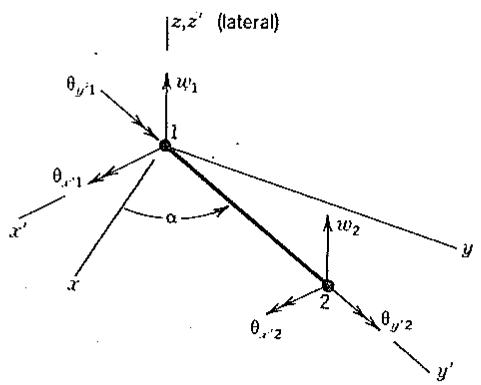
7.13 A plane grillage is a plane network of straight members that carries loads normal to its plane. Thus the grillage resembles a plane frame, but carries lateral loads. A typical member resists bending and torsional deformation and has six d.o.f., as shown. Write, in terms of angle $\alpha$ in the xy plane, the transformation matrix that would be used to convert $[k']$ to $[k]$ , where $[k]$ operates on d.o.f. w (lateral deflection), $\theta_{x}$ (rotation about the x axis), and $\theta_{y}$ (rotation about the y axis) at each node.
text_image
z,z' (lateral)
θy'1
w1
1
θx'1
α
x'
y
w2
2
θx'2
θy'2
y'
Problem 7.13
7.14 A space beam can resist axial load, twisting about its axis, bending about either principal axis of its cross section, and transverse loads. Assume that the beam is straight, uniform, and has six d.o.f. at each end.
(a) Let the beam lie on the $x'$ axis and let $y'$ and $z'$ be parallel to principal axes of the cross section. Write the 12 by 12 stiffness matrix $[\mathbf{k}']$ that operates on d.o.f. $\{\mathbf{d}'\} = \left[u_1' v_1' w_1' \theta_{x1}' \cdots \theta_{y2}' \theta_{z2}'\right]^T$ . Let $\theta$ vectors point in the positive coordinate directions.
(b) Now consider that the beam is arbitrarily oriented in xyz coordinates.
Stiffness matrix [k] is desired, where [k] operates on d.o.f. {d} that are parallel to x, y, and z axes. Write the transformation matrix [T].
7.15 The size, shape, and orientation in space of a plane triangular element are defined by the known global coordinates of its three corner nodes.
(a) Let node 3 be at the origin of local coordinates $x'y'z'$ . In addition, let nodes 3 and 1 define the $x'$ axis and let the plane of the element define the $x'y'$ plane. Describe how to compute the direction cosines of Fig. 7.2-1 from the given information.
(b) If the element is a constant-strain triangle, write the matrix [T] that will produce the 9 by 9 global matrix [k] from the 6 by 6 local matrix $[\mathbf{k}^{\prime}]$ .
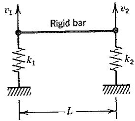
7.16 The bar shown is rigid and is supported by two linear springs of stiffness $k_{1}$ and $k_{2}$ . Only vertical displacement is permitted.
(a) Write the stiffness matrix that operates on d.o.f. $v_{1}$ and $v_{2}$ . Then transform this matrix so that you obtain a stiffness matrix that operates on $v_{1}$ and $\theta_{1}$ , where $\theta_{1}$ is a small rotation of the bar with respect to the horizontal and about the left end.
(b) Redefine $v_{2}$ so that it is the vertical displacement at the midpoint of the bar. Do not change $v_{1}$ . Then repeat part (a).
text_image
v₁
Rigid bar
v₂
k₁
k₂
L
Problem 7.16a
7.17 Work Problem 7.16 in reverse. That is, start with the final stiffness matrix that operates on $v_{1}$ and $\theta_{1}$ . By transformation, obtain from it the matrix in Problem 7.16a that operates on $v_{1}$ and $v_{2}$ . Similarly, obtain the matrix in Problem 7.16b that operates on $v_{1}$ and the midpoint $v_{2}$ .
7.18 Let a standard bar element of axial stiffness $k = AE / L$ be restricted to motion along its axis. Its [k] is 2 by 2 and operates on nodal d.o.f. $u_{1}$ and $u_{2}$ . Transform [k] so that it operates on nodal d.o.f. $u_{1}$ and $u_{r}$ , where $u_{r}$ is the displacement of node 2 relative to node 1.
7.19 A three-node bar element and its shape functions are shown in Fig. 6.2-1. Imagine that d.o.f. $u_{3}$ is to be replaced by $u_{r}$ , where $u_{r}$ is the displacement at $\xi = 0$ relative to the displacement at $\xi = 0$ dictated by $u_{1}$ and $u_{2}$ . Thus, $u_{3} = u_{r} + \frac{1}{2}(u_{1} + u_{2})$ . Write the transformation matrix and use it to determine the new shape functions.
# Section 7.6
7.20 Let loads $F_{x}$ and $F_{y}$ act at node 3 in Fig. 7.6-1. Verify that the operation $[\mathbf{T}]^{T}\{\mathbf{r}'\}$ transforms $F_{x}$ and $F_{y}$ to the correct $r$ and $s$ components.
7.21 Let Fig. 7.6-1 represent a plane truss for which axial stiffness $k = AE / L$ is the same for each bar. Also let the three interior angles in each panel be $45^{\circ}$ , $45^{\circ}$ , and $90^{\circ}$ . Apply a downward load $P$ at node 4 and set $u_{4} = 0$ . If $\beta = \arctan 0.75$ , what is the force in bar 3-1 in terms of $P$ ?
text_image
L
P
A, E, I
β
U
Problem 7.22
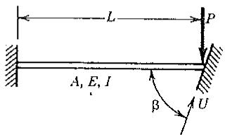
7.22 The right end of the cantilever beam slides without friction on a rigid wall, as shown. Represent the cantilever as a single element with axial, transverse, and rotational d.o.f. at the right end.
(a) Transform and impose the boundary conditions. Thus, obtain a 2 by 2 matrix [K] that operates on tangential displacement U and rotation $\theta$ at the right end.
(b) In addition, let the condition $\theta = 0$ be imposed. Solve for $U$ .
7.23 Imagine that, at a certain node of a space truss, motion is to be prohibited along a line whose direction cosines are $\ell_1, \ell_2$ , and $\ell_3$ . Motion is permitted in all directions normal to the line. Original nodal d.o.f. are displacements in coordinate directions $x, y$ , and $z$ .
(a) Explain precisely how to define suitable new directions for d.o.f. at the node, and write the transformation matrix at the node (analogous to $[\mathbf{T}_3]$ in Eq. 7.6-4).
(b) Check your result for the special case $\ell_2 = 1$ .
# Section 7.7
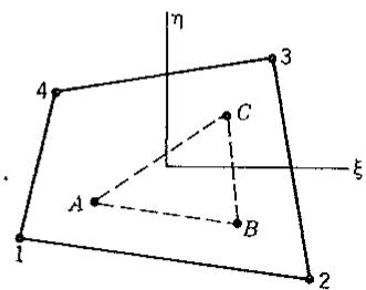
7.24 The element shown is of arbitrary quadrilateral shape and is formulated as a bilinear element (Section 6.3). A constant-strain triangle (six d.o.f.; lettered nodes) is to be attached, so that lettered nodes lie at $\xi = \pm 0.5$ and $\eta = \pm 0.5$ . Write [T] in the relation $\{\mathbf{d}'\} = [\mathbf{T}]\{\mathbf{d}\}$ , where $\{\mathbf{d}'\}$ and $\{\mathbf{d}\}$ contain d.o.f. of lettered nodes (“slaves”) and numbered nodes (“masters”) respectively.
text_image
1
2
3
4
A
B
C
ξ
η
Problem 7.24
7.25 At node 5 of the frame element in Fig. 7.7-1a, let forces $F_{x}$ and $F_{y}$ and moment $M_{s}$ (counterclockwise) be applied. How are these loads distributed to nodes 2 and 3 by the transformation of Eq. 7.7-4? Do the new loads exert the same force and moment resultants as the original loads?
7.26 Write the transformation matrix for the problem described in connection with Eq. 7.7-5. What is [k'] for this problem?
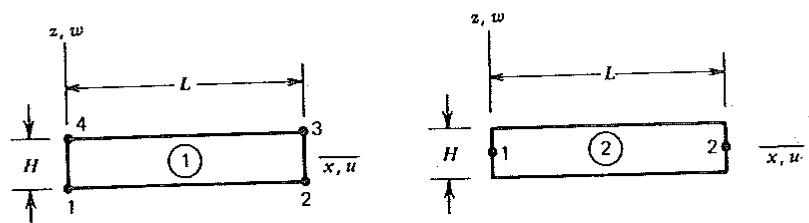
7.27 Plane element 1 in the sketch is bilinear (Section 6.3). It has the usual two d.o.f. per node. Plane frame element 2 has the usual three d.o.f. per node $(u_{i}, w_{i}, \theta_{i})$ . Consider the element stiffness matrices $[k_{1}]$ and $[k_{2}]$ .
Problem 7.27
(a) Write a transformation matrix $[\mathbf{T}_1]$ that could be used to convert $[\mathbf{k}_1]$ so that it operates on the d.o.f. of element 2.
(b) Write a transformation matrix $[\mathbf{T}_2]$ that could be used to convert $[\mathbf{k}_2]$ so that it operates on the d.o.f. of element 1.
(c) Should $[\mathbf{T}_1][\mathbf{T}_2]$ and $[\mathbf{T}_2][\mathbf{T}_1]$ be unit matrices? Find an argument that says so.
(d) Evaluate the products $[\mathbf{T}_1][\mathbf{T}_2]$ and $[\mathbf{T}_2][\mathbf{T}_1]$ . How can the results be explained?
# Section 7.8
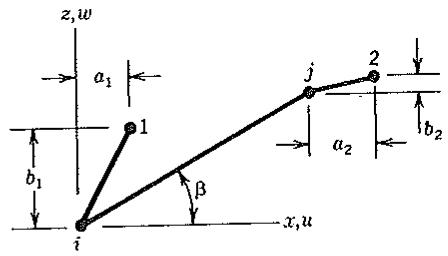
7.28 Element $ij$ is a plane frame element (see sketch). Imagine that d.o.f. at nodes $i$ and $j$ are to be made slave to d.o.f. at nodes 1 and 2 via rigid links $i1$ and $j2$ . Write the 6 by 6 transformation matrix [T].
text_image
z,w
a₁
b₁
i
β
x,u
j
2
a₂
b₂
Problem 7.28
7.29 Consider a frame element $ij$ , arbitrarily oriented in space. D.o.f. at node $i$ are $\{u_i \quad v_i \quad w_i \quad \theta_{xi} \quad \theta_{yi} \quad \theta_{zi}\}$ , where rotational d.o.f. vectors point in positive coordinate directions. D.o.f. at node $j$ are similar. The element is to be made slave to d.o.f. at some other nodes (nodes 1 and 2, say) via rigid links $i1$ and $j2$ , which are arbitrarily oriented. Write the 12 by 12 transformation matrix [T].
7.30 (a) Evaluate Eq. 7.8-4. That is, express $u_{6}$ in terms of $b, u_{5}, w_{1}, \theta_{1}, w_{2}$ , and $\theta_{2}$ (see Eq. 4.2-3 and Fig. 3.13-2).
(b) Write the 7 by 7 transformation matrix [T] in $\{\mathbf{d}'\} = [\mathbf{T}]\{\mathbf{d}\}$ , where $\{\mathbf{d}'\} = \left[u_3 \quad w_3 \quad \theta_3 \quad u_4 \quad w_4 \quad \theta_4 \quad u_6\right]^T$ .
text_image
1
2
b
P
text_image
Q
P
2
b
3
1
a
Problem 7.31
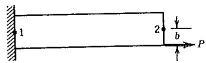
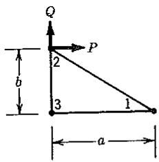
7.31 Obtain nodal loads $\{r\} = [T]^{T}\{r'\}$ for the elements and loads shown. Use [T] from Eq. 7.8-1 and Eq. 7.8-5 for the respective elements. Sketch $\{r\}$ , and argue why $\{r\}$ is reasonable or unreasonable.
7.32 Rewrite Eq. 7.8-5 if the triangle is of arbitrary shape, with nodal coordinates $x_{i}$ and $y_{i}$ ( $i = 1, 2, 3$ ).
7.33 Rewrite Eq. 7.8-5 if the “master” d.o.f. are changed from $u_{1}$ , $v_{1}$ , and $u_{2}$ to $u_{2}$ , $u_{3}$ , and $v_{3}$ .
# TOPICS IN STRUCTURAL MECHANICS
Miscellaneous elements, procedures, and remarks are presented. Some topics are of general interest while others pertain to structural mechanics.
# 8.1 D.O.F. WITHIN ELEMENTS. CONDENSATION
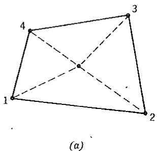
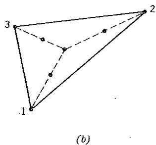
Occasionally, the basic building block of a finite element mesh is a macroelement—that is, a “patch” that consists of two or more elements coupled together. A macroelement can be regarded as a small structure. Its component elements are called subelements. Two examples appear in Fig. 8.1-1. Both macroelements are built of triangular subelements. In both cases the user of a computer program need define only the boundary nodes (which are numbered in the sketch). The program itself can automatically locate the internal nodes, generate and combine matrices of the subelements, and produce a stiffness matrix and load vector associated with only the boundary nodes. There is no limit to the number of subelements or the number of internal d.o.f. This observation leads to substructuring, discussed in Section 8.14.
D.o.f. of internal nodes are coupled only to d.o.f. of other internal nodes and to d.o.f. of nodes on the macroelement boundary. There is no coupling of internal d.o.f. to d.o.f. of nodes outside the macroelement. Accordingly, equations associated with internal d.o.f. can be processed separately from other equations of the structure. Separate processing can be both efficient and convenient for users, as will be seen subsequently. In the present section we emphasize the processing procedures.
Condensation. Condensation is the process of reducing the number of d.o.f. by substitution, for example, by starting a Gauss elimination solution of equations for unknowns but stopping before the stiffness matrix has been fully reduced. Condensation by elimination is also called static condensation. Condensation in dynamics is usually called reduction and introduces an approximation. Static condensation, described as follows, is strictly a manipulation and introduces no approximation.
Let the equations $[k]\{d\} = \{r\}$ represent a portion of the entire structure. This portion might be a macroelement built of subelements or a single element that has “nodeless” d.o.f. (such an element will be described in the following). Let d.o.f. $\{d\}$ be partitioned so that $\{d\} = \left[d_{r} - d_{c}\right]^{T}$ , where $\{d_{r}\}$ are boundary d.o.f. to be retained and $\{d_{c}\}$ are internal d.o.f. to be eliminated by condensation. Thus $[k]\{d\} = \{r\}$ becomes
$$
\left[ \begin{array}{l l} \mathbf {k} _ {r r} & \mathbf {k} _ {r c} \\ \mathbf {k} _ {c r} & \mathbf {k} _ {c c} \end{array} \right] \left\{ \begin{array}{l} \mathbf {d} _ {r} \\ \mathbf {d} _ {c} \end{array} \right\} = \left\{ \begin{array}{l} \mathbf {r} _ {r} \\ \mathbf {r} _ {c} \end{array} \right\} \tag {8.1-1}
$$
text_image
4
3
1
2
(a)
text_image
3
2
1
(b)
Figure 8.1-1. Elements having internal nodes. Boundary nodes are numbered; internal nodes are not. (a) A quadrilateral built of four triangles. (b) A triangle built of three triangles.
The lower partition is solved for $\{\mathbf{d}_c\}$ :
$$
\{\mathbf {d} _ {c} \} = - [ \mathbf {k} _ {c c} ] ^ {- 1} ([ \mathbf {k} _ {c r} ] \{\mathbf {d} _ {r} \} - \{\mathbf {r} _ {c} \}) \tag {8.1-2}
$$
Next, $\{\mathbf{d}_c\}$ is substituted into the upper partition of Eqs. 8.1-1. Thus
$$
\underbrace {([ \mathbf {k} _ {r r} ] - [ \mathbf {k} _ {r c} ] [ \mathbf {k} _ {c c} ] ^ {- 1} [ \mathbf {k} _ {c r} ])} _ {\text { condensed [k] }} \{\mathbf {d} _ {r} \} = \underbrace {\{\mathbf {r} _ {r} \} - [ \mathbf {k} _ {r c} ] [ \mathbf {k} _ {c c} ] ^ {- 1} \{\mathbf {r} _ {c} \}} _ {\text { condensed } \{\mathbf {r} \}} \tag {8.1-3}
$$
The element is now treated in standard fashion; that is, the condensed [k] and the condensed $\{r\}$ are assembled into the structure, boundary conditions are imposed, and structural d.o.f. $\{D\}$ are computed. Thus $\{d_{r}\}$ becomes known, and $\{d_{c}\}$ (which may be needed in stress calculation) follows from Eq. 8.1-2. Computation of $\{d_{c}\}$ is called recovery of internal d.o.f. Computer algorithms for condensation and recovery are discussed in Section 8.2.
Equation 8.1-3 is Gauss elimination, carried out on d.o.f. $\{d_{c}\}$ only (compare with Eq. B.2-2, Appendix B). Completion of the elimination process, and solution for $\{d_{r}\}$ , awaits assembly of all remaining elements of the structure. Thus condensation is simply the first set of eliminations in a solution of the structure equations $\{K\}\{D\} = \{R\}$ . The same solution vector $\{D\}$ would result if internal d.o.f. were eliminated later. The advantage of eliminating them first, at the element level and before assembly, is that the order of the structure stiffness matrix is reduced because d.o.f. $\{d_{c}\}$ are not carried into the global set of equations.
The partitioning used in Eq. 8.1-1 is a conceptual convenience rather than a computational necessity. D.o.f. to be condensed can appear anywhere in $\{d\}$ , and can be processed serially rather than simultaneously. After a d.o.f. $d_{k}$ is condensed, rows $i \neq k$ and columns $j \neq k$ comprise the condensed [k].
Nodeless D.o.f. Internal d.o.f. need not be associated with a node. The 18 d.o.f. plane element of Table 6.6-1 can be restated in terms of nodeless internal d.o.f., as we now describe. For i = 1 to 8, let shape functions $N_{i}$ be those of the 16 d.o.f. element, Eq. 6.6-1. Then displacements in the 18 d.o.f. element are
$$
u = \sum_ {i = 1} ^ {8} N _ {i} u _ {i} + N _ {9} a _ {1} \quad \text { and } \quad v = \sum_ {i = 1} ^ {8} N _ {i} v _ {i} + N _ {9} a _ {2} \tag {8.1-4}
$$
where, as in Eq. 6.6-3,
$$
N _ {9} = (1 - \xi^ {2}) (1 - \eta^ {2}) \tag {8.1-5}
$$
Mode $N_9$ is called a “bubble function” mode, and $a_1$ and $a_2$ are nodeless d.o.f. to be condensed, $\{d_c\} = [a_1 - a_2]^T$ . Physically, $a_1$ and $a_2$ represent the displacement components at $\xi = \eta = 0$ relative to the displacement components $\Sigma N_i u_i$ and $\Sigma N_i v_i$ at $\xi = \eta = 0$ dictated by d.o.f. at the eight boundary nodes. It is not necessary to assign such a physical meaning, or to calculate actual displacements at $\xi = \eta = 0$ , because d.o.f. $a_1$ and $a_2$ are not connected to other elements—that is, $a_1$ and $a_2$ in an element are not d.o.f. of another element as well.
In processing, nodeless d.o.f. are treated no differently than any other d.o.f. Thus, for the 18 d.o.f. element, it does not matter whether the $N_{i}$ are given by Table 6.6-1 or by Eqs. 8.1-4: if formulation procedures of preceding chapters are used consistently, then, from either starting point, identical 16 by 16 condensed matrices [k] and 16 by 1 consistent load vectors $\{\mathbf{r}_{e}\}$ appear after condensation of the two internal d.o.f. ( $u_{9}$ and $v_{9}$ or $a_{1}$ and $a_{2}$ ). Before condensation, loads in $\{\mathbf{r}_{e}\}$ associated with $a_{1}$ and $a_{2}$ may appear to be too large, even though correct, because $a_{1}$ and $a_{2}$ are not actual displacements.
When $a_1$ and $a_2$ are used as internal d.o.f., element geometry (e.g., the Jacobian matrix [J] of Eq. 6.6-4) is defined by the eight $N_i$ of Eqs. 6.6-1 and the coordinates of the eight boundary nodes. Use of Eq. 6.6-2 and the $N_i$ of Table 6.6-1 would yield the same geometry but with slightly more computational effort.
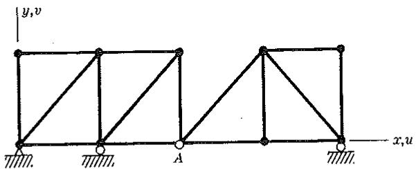
Releases. A “release” is a lack of complete connection between nodes that would usually be fully connected. The plane frame of Fig. 8.1-2 is a case in point. The structure displacement vector $\{D\}$ contains three d.o.f. per node. At node A, where there is a hinge, the two frames are not to share the same nodal rotation $\theta_{A}$ , as this would imply a rigid connection rather than a hinge. One way to model the hinge is to condense $\theta$ at A in (say) the left frame, then fill the row and column just condensed with zeros so that no rotational stiffness at A will be contributed to the structure by the left frame. Thus assembly makes the left and right frames share only $u_{A}$ and $v_{A}$ , and $\theta_{A}$ in $\{D\}$ now represents the rotation at A in the right frame. Rotation at A in the left frame is treated as an internal d.o.f. to be recovered after $\{D\}$ is known.
Another way to treat the hinge at A in Fig. 8.1-2 is to define two separate nodes at A, one in the left frame and one in the right but having the same location. Thus there are a total of six d.o.f. at A. Next, one joins only translational d.o.f. of the two nodes by means of a constraint technique (see Chapter 9). A similar treatment could be used at an interface between elastic bodies that may slide on one another.
text_image
y,v
A
x,u
Figure 8.1-2. Two frames with a hinge connection at A.