Input File Usage: \*ENRICHMENT, ELSET=element set name
Abaqus/CAE Usage: Interaction module: Special→Crack→Create→: XFEM: Select the crack domain: select region
# Defining a crack surface
As a crack propagates through the model, a crack surface representing both facets of cracked elements is generated on those enriched elements that are intersected by a crack during the analysis. You must associate the name of an enriched feature with the surface (see “Assigning a name to the enriched feature,” above).
The generated crack surface is supported only for the application of distributed pressure loads and the output of some surface variables.
Input File Usage: \*SURFACE, TYPE=XFEM
Abaqus/CAE Usage: An XFEM-based crack surface is not supported in Abaqus/CAE.
# Defining contact of cracked element surfaces using a small-sliding formulation
When an element is cut by a crack, the compressive behavior of the crack surfaces has to be considered. The formulae that govern behavior are very similar to those used for surface-based small-sliding penalty contact (“Mechanical contact properties: overview,” Section 37.1.1).
For an element intersected by a stationary crack or a moving crack with the linear elastic fracture mechanics approach, it is assumed that the elastic cohesive strength of the cracked element is zero. Therefore, compressive behavior of the crack surfaces is fully defined with the above options when the crack surfaces come into contact. For a moving crack with the cohesive segments method, the situation is more complex; traction-separation cohesive behavior as well as compressive behavior of the crack surfaces are involved in a cracked element. In the contact normal direction, the pressure-overclosure relationship governing the compressive behavior between the surfaces does not interact with the cohesive behavior, since they each describe the interaction between the surfaces in a different contact regime. The pressure-overclosure relationship governs the behavior only when the crack is “closed”; the cohesive behavior contributes to the contact normal stress only when the crack is “open” (i.e., not in contact).
If the elastic cohesive stiffness of an element is undamaged in the shear direction, it is assumed that the cohesive behavior is active. Any tangential slip is assumed to be purely elastic in nature and is resisted by the elastic cohesive strength of the element, resulting in shear forces. If damage has been defined, the cohesive contribution to the shear stresses starts degrading with damage evolution. Once maximum degradation has been reached, the cohesive contribution to the shear stresses is zero. The friction model activates and begins contributing to the shear stresses.
Input File Usage: Use the following options to define contact of crack surfaces using a smallsliding formulation:
\*ENRICHMENT, INTERACTION=interaction\_property\_name
\*SURFACE INTERACTION, NAME=interaction\_property\_name
\*SURFACE BEHAVIOR
Abaqus/CAE Usage: Interaction module: crack editor: toggle on Specify contact property
# Applying cohesive material concepts to XFEM-based cohesive behavior
The formulae and laws that govern the behavior of XFEM-based cohesive segments for a crack propagation analysis are very similar to those used for cohesive elements with traction-separation constitutive behavior (“Defining the constitutive response of cohesive elements using a tractionseparation description,” Section 32.5.6) and those used for surface-based cohesive behavior (“Surface-based cohesive behavior,” Section 37.1.10). The similarities extend to the linear elastic traction-separation model, damage initiation criteria, and damage evolution laws.
# Linear elastic traction-separation behavior
The available traction-separation model in Abaqus assumes initially linear elastic behavior followed by the initiation and evolution of damage. The elastic behavior is written in terms of an elastic constitutive matrix that relates the normal and shear stresses to the normal and shear separations of a cracked element.
The nominal traction stress vector, , consists of the following components: $t _ { n } , t _ { s } ,$ and (in threedimensional problems) $t _ { t }$ , which represent the normal and the two shear tractions, respectively. The corresponding separations are denoted by $\delta _ { n } , \delta _ { s }$ , and $\delta _ { t }$ . The elastic behavior can then be written as
$$
\mathbf {t} = \left\{ \begin{array}{l} t _ {n} \\ t _ {s} \\ t _ {t} \end{array} \right\} = \left[ \begin{array}{c c c} K _ {n n} & 0 & 0 \\ 0 & K _ {s s} & 0 \\ 0 & 0 & K _ {t t} \end{array} \right] \left\{ \begin{array}{l} \delta_ {n} \\ \delta_ {s} \\ \delta_ {t} \end{array} \right\} = \mathbf {K} \delta .
$$
The normal and tangential stiffness components will not be coupled: pure normal separation by itself does not give rise to cohesive forces in the shear directions, and pure shear slip with zero normal separation does not give rise to any cohesive forces in the normal direction.
The terms $K _ { n n } , K _ { s s }$ , and $K _ { t t }$ are calculated based on the elastic properties for an enriched element. Specifying the elastic properties of the material in an enriched region is sufficient to define both the elastic stiffness and the traction-separation behavior.
# Damage modeling
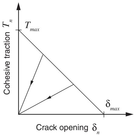
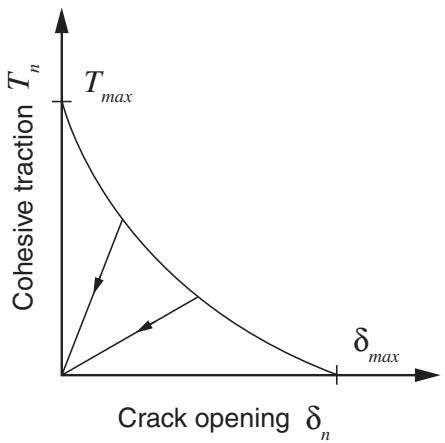
Damage modeling allows you to simulate the degradation and eventual failure of an enriched element. The failure mechanism consists of two ingredients: a damage initiation criterion and a damage evolution law. The initial response is assumed to be linear as discussed in the previous section. However, once a damage initiation criterion is met, damage can occur according to a user-defined damage evolution law. Figure 10.7.1–6 shows a typical linear and a typical nonlinear traction-separation response with a failure mechanism. The enriched elements do not undergo damage under pure compression.
Damage of the traction-separation response for cohesive behavior in an enriched element is defined within the same general framework used for conventional materials (see “Progressive damage and failure,” Section 24.1.1). However, unlike cohesive elements with traction-separation behavior, you do not have to specify the undamaged traction-separation behavior in an enriched element.
text_image
T_n
T_max
Crack opening δ_n
δ_max
line
| Crack opening δₙ | Cohesive traction Tₙ |
| ---------------- | --------------------- |
| 0 | Tₘₐₓ |
| δₘₐₓ | Tₙ (estimated) |
(b)
Figure 10.7.1–6 Typical linear (a) and nonlinear (b) traction-separation response.
# Crack initiation and direction of crack extension
Crack initiation refers to the beginning of degradation of the cohesive response at an enriched element. The process of degradation begins when the stresses or the strains satisfy specified crack initiation criteria. Crack initiation criteria are available based on the following Abaqus/Standard built-in models:
• the maximum principal stress criterion,
• the maximum principal strain criterion,
• the maximum nominal stress criterion,
• the maximum nominal strain criterion,
• the quadratic traction-interaction criterion, and
• the quadratic separation-interaction criterion.
In addition, a user-defined damage initiation criterion can be specified in user subroutine UDMGINI.
An additional crack is introduced or the crack length of an existing crack is extended after an equilibrium increment when the fracture criterion, $f ,$ reaches the value 1.0 within a given tolerance:
$$
1. 0 \leq f \leq 1. 0 + f _ {t o l}.
$$
You can specify the tolerance $f _ { t o l . } \mathrm { ~ I f ~ } f > 1 + f _ { t o l }$ , the time increment is cut back such that the crack initiation criterion is satisfied. The default value of $f _ { t o l }$ is 0.05.
Input File Usage: $\scriptstyle * \mathrm { D A M A G E ~ I N I T I A T I O N } , \mathrm { T O L E R A N C E } = f _ { t o l }$
Abaqus/CAE Usage: Property module: material editor: Mechanical: Damage for Traction Separation Laws: Quade Damage, Maxe Damage, Quads Damage, Maxs Damage, Maxpe Damage, or Maxps Damage: Tolerance: $f _ { t o l }$
# Specifying the crack direction
When the maximum principal stress or the maximum principal strain criterion is specified, the newly introduced crack is always orthogonal to the maximum principal stress/strain direction when the fracture criterion is satisfied. However, when one of the other Abaqus/Standard built-in crack initiation criteria is used, you have to specify if the newly introduced crack will be orthogonal to the element local 1- direction or orthogonal to the element local 2-direction (see “Conventions,” Section 1.2.2) when the fracture criterion is satisfied. By default, the crack is orthogonal to the element local 1-direction. If a user-defined damage initiation criterion is specified, the normal direction to the crack plane or the crack line can be defined in user subroutine UDMGINI.
Input File Usage: Use one of the following options to specify the crack direction when the maximum nominal stress, the maximum nominal strain, the quadratic traction-interaction, or the quadratic separation-interaction criterion is specified: \*DAMAGE INITIATION, NORMAL DIRECTION=1 (default) \*DAMAGE INITIATION, NORMAL DIRECTION=2
Abaqus/CAE Usage: Property module: material editor: Mechanical→Damage for Traction Separation Laws: Quade Damage, Maxe Damage, Quads Damage, or Maxs Damage: Direction relative to local 1-direction (for XFEM): Normal or Parallel
Maximum principal stress criterion
The maximum principal stress criterion can be represented as
$$
\mathrm{f} = \left\{\frac {\left\langle \sigma_ {m a x} \right\rangle}{\sigma_ {m a x} ^ {o}} \right\}.
$$
Here, $\sigma _ { m a x } ^ { o }$ represents the maximum allowable principal stress. The symbol represents the Macaulay bracket with the usual interpretation (i.e., $\langle \sigma _ { m a x } \rangle = 0$ if $\sigma _ { m a x } < 0$ and $\left. \sigma _ { m a x } \right. = \sigma _ { m a x } \mathrm { ~ i f ~ } \sigma _ { m a x } \geq 0 )$ . The Macaulay brackets are used to signify that a purely compressive stress state does not initiate damage. Damage is assumed to initiate when the maximum principal stress ratio (as defined in the expression above) reaches a value of one.
Input File Usage: \*DAMAGE INITIATION, CRITERION=MAXPS
Abaqus/CAE Usage: Property module: material editor: Mechanical: Damage for Traction Separation Laws: Maxps Damage
Maximum principal strain criterion
The maximum principal strain criterion can be represented as
$$
\mathrm{f} = \left\{\frac {\left\langle \varepsilon_ {m a x} \right\rangle}{\varepsilon_ {m a x} ^ {o}} \right\}.
$$
Here, $\varepsilon _ { m a x } ^ { o }$ represents the maximum allowable principal strain, and the Macaulay brackets signify that a purely compressive strain does not initiate damage. Damage is assumed to initiate when the maximum principal strain ratio (as defined in the expression above) reaches a value of one.
Input File Usage: \*DAMAGE INITIATION, CRITERION=MAXPE
Abaqus/CAE Usage: Property module: material editor: Mechanical: Damage for Traction Separation Laws: Maxpe Damage
Maximum nominal stress criterion
The maximum nominal stress criterion can be represented as
$$
\mathrm{f} = \max \biggl \{\frac {\langle t _ {n} \rangle}{t _ {n} ^ {o}}, \frac {t _ {s}}{t _ {s} ^ {o}}, \frac {t _ {t}}{t _ {t} ^ {o}} \biggr \}.
$$
The nominal traction stress vector, , consists of three components (two in two-dimensional problems). $t _ { n }$ is the component normal to the likely cracked surface, and $t _ { s }$ and $t _ { t }$ are the two shear components on the likely cracked surface. Depending on what you specify (see “Specifying the crack direction,” above), the likely cracked surface will be orthogonal either to the element local 1-direction or to the element local 2-direction. Here, $t _ { n } ^ { o } , t _ { s } ^ { o } ,$ , and $t _ { t } ^ { o }$ represent the peak values of the nominal stress. The symbol represents the Macaulay bracket with the usual interpretation. The Macaulay brackets are used to signify that a purely compressive stress state does not initiate damage. Damage is assumed to initiate when the maximum nominal stress ratio (as defined in the expression above) reaches a value of one.
Input File Usage: \*DAMAGE INITIATION, CRITERION=MAXS
Abaqus/CAE Usage: Property module: material editor: Mechanical: Damage for Traction Separation Laws: Maxs Damage
Maximum nominal strain criterion
The maximum nominal strain criterion can be represented as
$$
\mathrm{f} = \max \biggl \{\frac {\left\langle \varepsilon_ {n} \right\rangle}{\varepsilon_ {n} ^ {o}}, \frac {\varepsilon_ {s}}{\varepsilon_ {s} ^ {o}}, \frac {\varepsilon_ {t}}{\varepsilon_ {t} ^ {o}} \biggr \}.
$$
Damage is assumed to initiate when the maximum nominal strain ratio (as defined in the expression above) reaches a value of one.
Input File Usage: \*DAMAGE INITIATION, CRITERION=MAXE
Abaqus/CAE Usage: Property module: material editor: Mechanical: Damage for Traction Separation Laws: Maxe Damage
Quadratic nominal stress criterion
The quadratic nominal stress criterion can be represented as
$$
\mathrm{f} = \left\{\frac {\langle t _ {n} \rangle}{t _ {n} ^ {o}} \right\} ^ {2} + \left\{\frac {t _ {s}}{t _ {s} ^ {o}} \right\} ^ {2} + \left\{\frac {t _ {t}}{t _ {t} ^ {o}} \right\} ^ {2}.
$$
Damage is assumed to initiate when the quadratic interaction function involving the stress ratios (as defined in the expression above) reaches a value of one.
Input File Usage: \*DAMAGE INITIATION, CRITERION=QUADS
Abaqus/CAE Usage: Property module: material editor: Mechanical: Damage for Traction Separation Laws: Quads Damage
Quadratic nominal strain criterion
The quadratic nominal strain criterion can be represented as
$$
\mathrm{f} = \left\{\frac {\left\langle \varepsilon_ {n} \right\rangle}{\varepsilon_ {n} ^ {o}} \right\} ^ {2} + \left\{\frac {\varepsilon_ {s}}{\varepsilon_ {s} ^ {o}} \right\} ^ {2} + \left\{\frac {\varepsilon_ {t}}{\varepsilon_ {t} ^ {o}} \right\} ^ {2}.
$$
Damage is assumed to initiate when the quadratic interaction function involving the nominal strain ratios (as defined in the expression above) reaches a value of one.
Input File Usage: \*DAMAGE INITIATION, CRITERION=QUADE
Abaqus/CAE Usage: Property module: material editor: Mechanical: Damage for Traction Separation Laws: Quade Damage
User-defined damage initiation criterion
User subroutine UDMGINI provides a general capability for implementing a user-defined damage initiation criterion.
You can define several damage initiation mechanisms in user subroutine UDMGINI. You represent each damage initiation mechanism by a fracture criterion, $f _ { i n d e x i }$ , and its associated normal direction to the crack plane or the crack line. Although you can define several damage initiation mechanisms, the actual damage initiation for an enriched element is governed by the most severe damage initiation mechanism:
$$
\mathrm{f} = \max \{f _ {i n d e x 1}, f _ {i n d e x 2}, \dots f _ {i n d e x n} \}.
$$
Damage is assumed to initiate when f, as defined in the expression above, reaches a value of one.
You must specify any material constants that are needed in user subroutine UDMGINI as part of a user-defined damage initiation criterion definition.
Input File Usage: Use the following option to define a user-defined damage initiation criterion:
\*DAMAGE INITIATION, CRITERION=USER
Use the following option to specify the total number of failure mechanisms in the user-defined damage initiation criterion:
\*DAMAGE INITIATION, CRITERION=USER, FAILURE MECHANISMS=
Use the following option to define properties for a user-defined damage initiation criterion:
\*DAMAGE INITIATION, CRITERION=USER, PROPERTIES=number\_of\_constants
Abaqus/CAE Usage: Defining a user-defined damage initiation criterion is not supported in Abaqus/CAE.
# Local calculations of the stress and strain fields ahead of the crack tip
An accurate and efficient evaluation of the stress/strain fields ahead of the crack tip is important for both evaluating the crack initiation criterion and computing the crack propagation direction when needed. Abaqus/Standard offers several options for computing these fields.
# Centroidal values of stress and strain
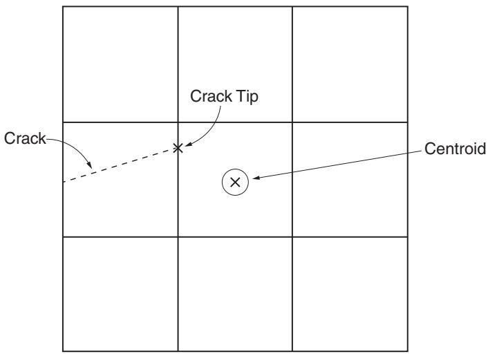
By default, the stress/strain computed at the element centroid ahead of the crack tip is used to determine if the damage initiation criterion is satisfied and to determine the crack propagation direction. See Figure 10.7.1–7.
Input File Usage: \*DAMAGE INITIATION, POSITION=CENTROID (default)
Abaqus/CAE Usage: Property module: material editor: Mechanical→Damage for Traction Separation Laws: Quade Damage, Maxe Damage, Quads Damage, Maxs Damage, Maxpe Damage, or Maxps Damage: Position→Centroid
# Computing the stress and strain fields at the crack tip
With a sufficiently refined mesh, the centroidal approximation is accurate and economical. However, if the finite element mesh in the vicinity of the crack tip is coarse relative to the gradients in the stress/strain fields, the default centroidal approximation may not be sufficient. In such cases you can use the stress/strain extrapolated to the crack tip to determine if the damage initiation criterion is satisfied and to determine the crack propagation direction. See Figure 10.7.1–7.
Input File Usage: \*DAMAGE INITIATION, POSITION=CRACKTIP
Abaqus/CAE Usage: Property module: material editor: Mechanical→Damage for Traction Separation Laws: Quade Damage, Maxe Damage, Quads Damage, Maxs Damage, Maxpe Damage, or Maxps Damage: Position→Crack tip
text_image
Crack Tip
Crack
Centroid
Figure 10.7.1–7 Centroidal and crack tip locations.
Combining crack tip and centroidal calculations
You can also choose to combine the two previous alternatives: you can use the stress/strain values extrapolated to the crack tip to determine if the damage initiation criterion is satisfied, and you can use the stress/strain values at the element centroid to determine the crack propagation direction.
Input File Usage: \*DAMAGE INITIATION, POSITION=COMBINED
Abaqus/CAE Usage: Property module: material editor: Mechanical→Damage for Traction Separation Laws: Quade Damage, Maxe Damage, Quads Damage, Maxs Damage, Maxpe Damage, or Maxps Damage: Position→Combined
# Nonlocal averaging of the stress and strain fields to improve the accuracy of crack propagation directions
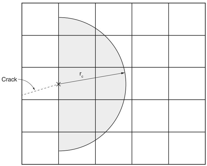
The three options for evaluating the stress and strain fields discussed above are local calculations in the sense that the evaluated fields are local to the single element ahead of the crack tip. In the case of coarse and/or unstructured meshes a nonlocal averaging of the stress and strain fields ahead of the crack tip can lead to a more accurate evaluation of those fields, which can improve the accuracy of the computed propagation directions. See Figure 10.7.1–8.
Input File Usage: \*DAMAGE INITIATION, POSITION=NONLOCAL
Abaqus/CAE Usage: Nonlocal averaging of the stress/strain fields ahead of the crack tip is not supported in Abaqus/CAE.
text_image
Crack
r_c
Figure 10.7.1–8 Nonlocal averaging region.
Specifying the region of the model used for nonlocal averaging
To control the range of elements used for nonlocal averaging in the crack direction calculations, you can specify a radius, $r _ { c } .$ , within which the elements ahead of the crack tip are included. The default radius is three times the typical element characteristic length in the enriched region.
Input File Usage: \*DAMAGE INITIATION, R CRACK DIRECTION=
Abaqus/CAE Usage: Specifying the range of the model for nonlocal averaging is not supported in Abaqus/CAE.
Smoothing the stress/strain fields before averaging
To further improve the nonlocal averaging, you can request an initial smoothing of the stress/strain fields ahead of the crack. In this case Abaqus/Standard averages the field values to element nodes and then interpolates the smoothed fields to the integration points. Once smoothing is complete, the nonlocal averaging is applied. No smoothing is applied by default.
Input File Usage: Use one of the following options:
\*DAMAGE INITIATION, SMOOTHING=NONE (default)
\*DAMAGE INITIATION, SMOOTHING=NODAL
Abaqus/CAE Usage: Smoothing the stress/strain fields before averaging is not supported in Abaqus/CAE.
Weighting schemes for nonlocal averaging
Abaqus/Standard offers a number of weighting schemes for field smoothing that provide additional control over nonlocal averaging. For example, you may want to give a higher weighting to elements close to the crack tip. You can specify a weight function, , to compute the average stress/strain based on the distance from the element integration points to the crack tip, . By default, a uniform weighting is applied to all elements used for averaging; alternatively, you can use a Gaussian function or a cubic spline function. You can also define a weight function with a user subroutine.
The Gaussian function is represented by:
$$
\omega (r) = \frac {1}{(2 \pi) ^ {3 / 2} r _ {c} ^ {3}} e x p (\frac {- r ^ {2}}{2 r _ {c} ^ {2}})
$$
$$
\omega (r) = \left\{ \begin{array}{l l} 4 (\frac {r}{r _ {c}} - 1) (\frac {r}{r _ {c}}) ^ {2} + \frac {2}{3}, & 0 < r < \frac {r _ {c}}{2} \\ \frac {4}{3} (1 \frac {r}{r _ {c}}) ^ {3}, & \frac {r _ {c}}{2} \leq r \leq r _ {c} \\ 0, & \text {otherwise} \end{array} \right.
$$
Input File Usage: Use one of the following options:
\*DAMAGE INITIATION, WEIGHTING METHOD=UNIFORM (default)
\*DAMAGE INITIATION, WEIGHTING METHOD=GAUSS
\*DAMAGE INITIATION, WEIGHTING METHOD=CUBIC SPLINE
\*DAMAGE INITIATION, WEIGHTING METHOD=USER
Abaqus/CAE Usage: Specifying a weighting scheme for nonlocal averaging is not supported in Abaqus/CAE.
# Damage evolution
The damage evolution law describes the rate at which the cohesive stiffness is degraded once the corresponding initiation criterion is reached. The general framework for describing the evolution of damage is conceptually similar to that used for damage evolution in surface-based cohesive behavior (“Surface-based cohesive behavior,” Section 37.1.10).
A scalar damage variable, D, represents the averaged overall damage at the intersection between the crack surfaces and the edges of cracked elements. It initially has a value of 0. If damage evolution is modeled, D monotonically evolves from 0 to 1 upon further loading after the initiation of damage. The normal and shear stress components are affected by the damage according to
$$
t _ {n} = \left\{ \begin{array}{l l} (1 - D) T _ {n}, & T _ {n} \geq 0 \\ T _ {n}, & \text { otherwise (no damage to compressive stiffness) }; \end{array} \right.
$$
$$
t _ {s} = (1 - D) T _ {s},
$$
$$
t _ {t} = (1 - D) T _ {t},
$$