| SLIDE-PLANE |
| Basic, assembled, or complex: | Basic |
| Kinematic constraints: | $x = x_0$ |
| Constraint force output: | $f_1$ |
| Available components: | $u_2, u_3$ |
| Kinetic force output: | $f_2, f_3$ |
| Orientation at a: | Required |
| Orientation at b: | Ignored |
| Connector stops: | $l_2^{min} \leq y \leq l_2^{max}$ , $l_3^{min} \leq z \leq l_3^{max}$ |
| Constitutive reference lengths: | $l_2^{ref}, l_3^{ref}$ |
| Predefined friction parameters: | Optional: $F_{C}^{int}$ |
| Contact force for predefined friction: | $F_{C}$ |
# SLIPRING
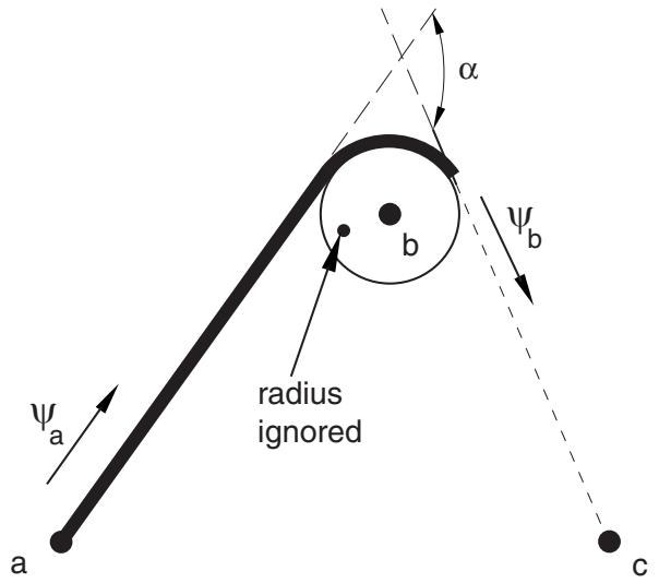
Connection type SLIPRING provides a connection between two nodes that models material flow and stretching between two points of a belt system. It can be used to model seat belts (see “Seat belt analysis of a simplified crash dummy,” Section 3.3.1 of the Abaqus Example Problems Guide), pulley systems, and taut cable systems. The angle between two adjacent belt segments is used only for friction calculations. By default, the angle, , is computed automatically from the nodal coordinates as an angle between and . Alternatively, you can specify the angle between two adjacent belt segments (in radians) as part of the connector section definition. You can use this option to specify wrapping angles larger than .
This connection type activates the material flow degree of freedom (10) at both nodes of the connector. As with any other nodal degree of freedom, you must be careful in constraining it. This is typically done by attaching the connector to other SLIPRING connectors that are part of the belt system, attaching it to a RETRACTOR (FLOW-CONVERTER) connector, or applying a boundary condition.
SLIPRING connections cannot be used in two-dimensional and axisymmetric analyses in Abaqus/Explicit.