quantities that describe the current deformation state of a gasket. Abaqus/Standard computes the local directions by default. You can also define them for some element types.
# Default local directions
Abaqus/Standard computes the local 1-direction as explained in “Defining the gasket element’s initial geometry,” Section 32.6.4.
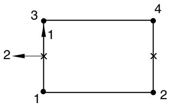
For two-dimensional and axisymmetric gasket elements, the local 2-direction is defined so that the cross product between the local 1- and 2-directions gives the out-of-plane direction (see Figure 32.6.1–3).
flowchart
```mermaid
graph TD
1 -->|1| 3
3 -->|2| 2
2 --> 1
1 --> 4
4 --> 3
```
Figure 32.6.1–3 Local directions for two-dimensional and axisymmetric gasket elements.
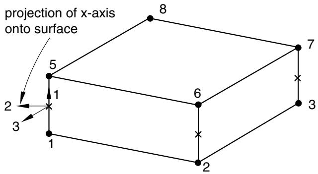
For three-dimensional area and three-dimensional link elements, the local 2- and 3-directions are normal to the local 1-direction (see Figure 32.6.1–4) and are defined by the standard Abaqus convention for local directions on surfaces in space (see “Conventions,” Section 1.2.2).
text_image
projection of x-axis onto surface
5
8
7
1
6
3
2
3
1
2
2
Figure 32.6.1–4 Local directions for three-dimensional area and three-dimensional link gasket elements.
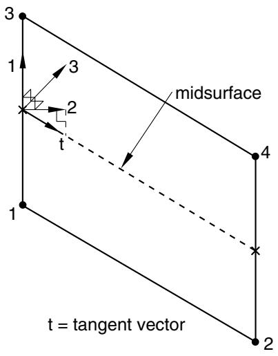
For three-dimensional line elements, the local 2-direction is obtained by the projection of the tangent to the midsurface of the element onto the plane orthogonal to the local 1-direction (see Figure 32.6.1–5). The local 3-direction is then obtained by the cross product of the local 1- and 2-directions.
text_image
3
1
3
2
t
midsurface
4
1
t = tangent vector
2
Figure 32.6.1–5 Local directions for three-dimensional line gasket elements.
# Specifying the local directions
You can define the local 1-direction as explained in “Defining the gasket element’s initial geometry,” Section 32.6.4. The local 2- and 3-directions can be defined using local orientations (“Orientations,” Section 2.2.5) for three-dimensional area and three-dimensional link elements that consider transverse shear and membrane deformations.
Input File Usage: Use the following option to associate a local orientation with a particular gasket element set:
$* \mathrm { G A S K E T ~ S E C T I O N } , \mathrm { E L S E T } = n a m e , \mathrm { O R I E N T A T I O N } = n a m e$
Abaqus/CAE Usage: Property module: Assign→Material Orientation
# Procedures with which gasket elements are allowed
Gasket elements can be used in static, static perturbation, quasi-static, dynamic, and frequency analyses. However, gasket elements are assumed to have no mass; therefore, the density cannot be defined for gasket elements.
# 32.6.2 CHOOSING A GASKET ELEMENT
Products: Abaqus/Standard Abaqus/CAE
# References
• “Gasket elements: overview,” Section 32.6.1
• “Two-dimensional gasket element library,” Section 32.6.7
• “Three-dimensional gasket element library,” Section 32.6.8
• “Axisymmetric gasket element library,” Section 32.6.9
• Chapter 32, “Gaskets,” of the Abaqus/CAE User’s Guide
# Overview
The Abaqus/Standard gasket element library includes:
• elements for two-dimensional analyses;
• elements for three-dimensional analyses;
• elements for axisymmetric analyses;
• elements that account for the thickness-direction behavior of gaskets only; and
• elements that account for the thickness-direction, membrane, and transverse shear behaviors of gaskets.
# Naming convention
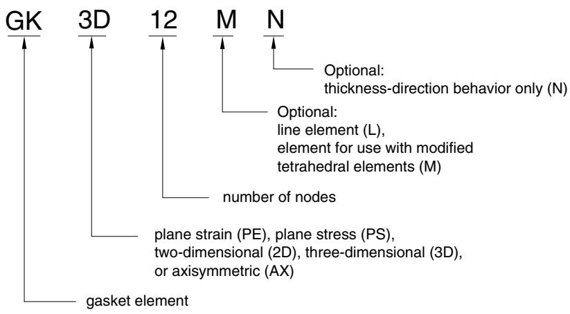
The gasket elements used in Abaqus/Standard are named as follows:
text_image
GK 3D 12 M N
Optional: thickness-direction behavior only (N)
Optional: line element (L), element for use with modified tetrahedral elements (M)
number of nodes
plane strain (PE), plane stress (PS), two-dimensional (2D), three-dimensional (3D), or axisymmetric (AX)
gasket element
For example, GKPE4 is a 4-node, plane strain gasket element that accounts for thickness-direction, membrane, and transverse shear behaviors.
# Elements for general use versus elements with thickness-direction behavior only
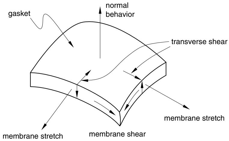
Abaqus/Standard offers two classes of gasket elements. In both classes material properties can be specified by either special gasket behavior models or built-in material models, including user-defined materials (see “Defining the gasket behavior directly using a gasket behavior model,” Section 32.6.6, and “Defining the gasket behavior using a material model,” Section 32.6.5). The first class is a collection of gasket elements that have all displacement degrees of freedom active at their nodes. These elements are necessary when the membrane and/or transverse shear behavior of the gasket is of importance (see Figure 32.6.2–1). The thickness-direction, transverse shear, and membrane behaviors can be defined as uncoupled behaviors only, when the elements are used in conjunction with special gasket behavior models. In some cases the membrane effects are only secondary; in such cases it is possible to model only the thickness-direction and transverse shear behaviors. These elements are suited for analyses where both thickness-direction behavior and frictional effects are important.
text_image
gasket
normal
behavior
transverse shear
membrane stretch
membrane shear
membrane stretch
Figure 32.6.2–1 Different deformation modes of gaskets.
In the second class of gasket elements deformation is measured only in the thickness direction. The response of the gasket to any other deformation mode is ignored. The nodes of these elements have only one displacement degree of freedom, which lies in the thickness direction of the gasket. This class of elements is intended as a means to reduce the computational cost of an analysis when the thicknessdirection behavior of the gasket is the only behavior of importance. This behavior can be specified easily in terms of pressure in the gasket versus gasket closure. Frictional forces cannot be transmitted by such elements, and any thermal expansion or stretching of the gasket in its plane is not accounted for.
# Elements for two-dimensional, three-dimensional, and axisymmetric analyses
For both classes of gasket elements Abaqus/Standard offers a choice of two-dimensional, three-dimensional, and axisymmetric elements. Plane stress and plane strain elements are provided for two-dimensional analyses to represent thin gaskets or thick gaskets in the out-of-plane direction, respectively. Axisymmetric gasket elements are provided for cases where the geometry and loading of the structure are axisymmetric.
Abaqus/Standard offers 2-node or link elements for two-dimensional, three-dimensional, and axisymmetric analyses; three-dimensional line elements; and a three-dimensional 12-node element for use with modified tetrahedral elements. These elements have specific characteristics that are useful when modeling gaskets.
# Link elements
Because link gasket elements have two nodes, their geometry defines only one dimension of the gasket—the through-thickness dimension. A link gasket element might typically be used to model a washer used under a bolt, when the bolt itself is modeled with a truss element. For two-dimensional and three-dimensional link elements the cross-section of the gasket is undetermined. For axisymmetric link elements the width of the element is undetermined. The reduction in dimensionality of these elements offers flexibility in the specification of the gasket behavior and can prove to be very efficient in some cases; see “Defining the gasket behavior directly using a gasket behavior model,” Section 32.6.6, for further details.
# Three-dimensional line elements
Three-dimensional line gasket elements are typically used to model narrow, thicker features in gaskets, such as an elastomeric insert around a hole. Since they are used in three-dimensional analyses, their width is undetermined from the element’s geometry. This reduction in dimensionality offers flexibility in the specification of the gasket behavior and can prove to be very efficient in some cases; see “Defining the gasket behavior directly using a gasket behavior model,” Section 32.6.6, for further details.
# 12-node elements for use with modified tetrahedral elements
The 12-node gasket elements have the same contact properties as the modified 10-node tetrahedra; these elements have consistent nodal forces at the corner and midside nodes. They are primarily intended for use with the modified tetrahedral elements but can also be used in conjunction with other solid continuum elements by using contact pairs. In the latter case the solution may be noisy for badly mismatched meshes.
# 32.6.3 INCLUDING GASKET ELEMENTS IN A MODEL
Products: Abaqus/Standard Abaqus/CAE
# References
• “Gasket elements: overview,” Section 32.6.1
• “Choosing a gasket element,” Section 32.6.2
• “Contact interaction analysis: overview,” Section 36.1.1
• “General multi-point constraints,” Section 35.2.2
• Chapter 32, “Gaskets,” of the Abaqus/CAE User’s Guide
# Overview
# Gasket elements:
• are used to model gaskets and other seals between two components, each of which may be deformable or rigid; and
• are connected to the adjacent components by sharing nodes, by using surface-based tie constraints, by using MPCs type TIE or PIN, or by using contact pairs.
This section discusses the techniques that are available to discretize gaskets and assemble them in a model representing several components, such as an internal combustion engine. The methods described all apply to gasket elements that have all displacement degrees of freedom active at their nodes. For the most part they also apply to gasket elements with only thickness-direction behavior; exceptions are discussed later in this section.
# Discretizing gaskets using gasket elements
Gaskets are generally manufactured as independent components. The gasket behavior is usually measured by performing a compression experiment on the gasket. In this case the gasket can be discretized as a single layer of gasket elements.
Gaskets are sometimes made of several layers of materials. If the behavior of the gasket is obtained by compression testing of the entire gasket, the gasket can again be discretized as a single layer of gasket elements. However, if the behavior of the gasket is obtained by compression testing of each layer constituting the gasket, the gasket can be discretized with a corresponding set of layers of gasket elements.
# Discretizing gaskets with multiple layers
If layers of gasket elements are used in the thickness direction and these layers do not have the same element layout in the plane of the gasket, use surface-based tie constraints, mesh refinement MPCs, or tied contact pairs to connect the different layers of the gasket. If tied contact pairs are used, assign a positive value to the adjustment zone depth, a, for the contact pairs (see “Adjusting initial surface
positions and specifying initial clearances in Abaqus/Standard contact pairs,” Section 36.3.5) so that all slave nodes are properly tied at the beginning of the analysis.
# Assembling gaskets to other components in a model
The easiest method to connect gasket elements that use all displacement components at their nodes to other components in a model is to define the mesh so that the gasket elements can share nodes with the elements on the surfaces of the adjacent components. More generally, when the gasket mesh is not matched to the meshing of the surfaces of the adjacent components or when the gasket elements that consider only thickness-direction behavior are used, gasket elements can be connected to other components by using contact pairs.
# Connecting gaskets to other components by using contact pairs or surface-based constraints
Gaskets are usually composed of materials that are softer than the materials that compose the neighboring components. In addition, the discretization of gaskets will usually be finer than the discretization of neighboring parts. These two facts suggest that the contacting surfaces of a gasket should be the slave surfaces and that the contacting surfaces of neighboring parts should be the master surfaces. The second consideration also suggests that mismatched meshes will often be used in analyses involving gaskets. If mismatched meshes are used, the pressure distribution on a compressed gasket may not be predicted accurately; submodeling (“Submodeling: overview,” Section 10.2.1) may be required to obtain accurate local results. Two techniques are available to connect gasket elements to other parts in the model when surface-based constraints are used.
# Using a regular contact pair and a tied contact pair or a surface-based constraint
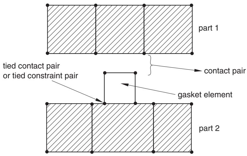
This technique is required when the gasket membrane behavior is not defined. Use a tied contact pair (“Defining tied contact in Abaqus/Standard,” Section 36.3.7) or a tie constraint (“Mesh tie constraints,” Section 35.3.1) on one side of the gasket and a regular contact pair on the other side, as shown in Figure 32.6.3–1. Because a regular contact pair is used on one side of the gasket, tensile stresses cannot develop in the gasket thickness direction should the components surrounding the gasket be pulled apart.
Assign a positive value to the adjustment zone depth, a, for the tied contact pair (see “Adjusting initial surface positions and specifying initial clearances in Abaqus/Standard contact pairs,” Section 36.3.5) or, if necessary, specify a position tolerance for the tie constraint (see “Mesh tie constraints,” Section 35.3.1) so that all slave nodes are properly tied at the beginning of the analysis. This technique allows for frictional slip on only one side of the gasket.
# Using a regular contact pair and a contact pair that does not allow separation
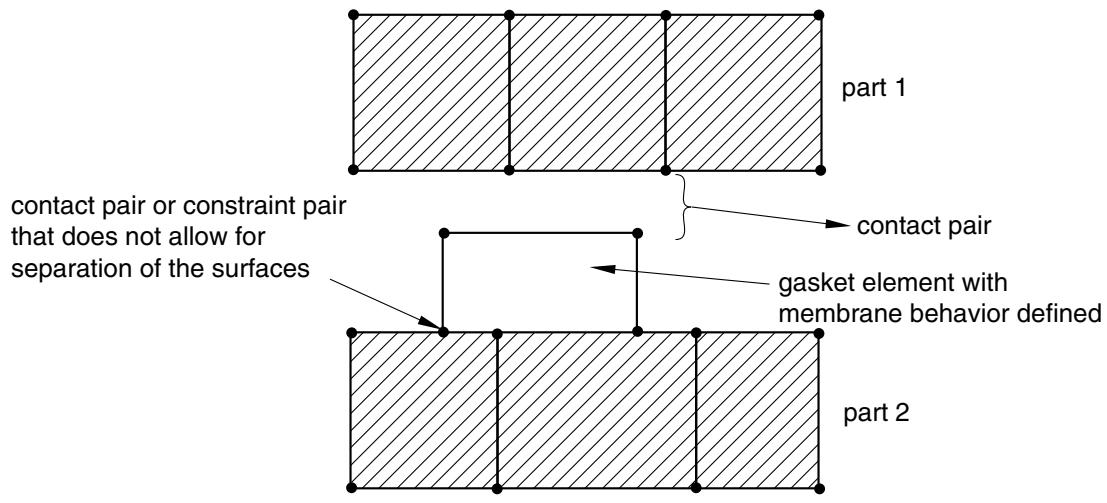
This technique allows for frictional slip to be transmitted on both sides of the gasket. It is recommended when membrane behavior is defined for the gasket since it allows for the gasket membrane to stretch or contract as a result of frictional effects considered on both sides of the gasket. A contact pair or a constraint pair that does not allow for separation of the surfaces (“Contact pressure-overclosure relationships,” Section 37.1.2) should be used on one side of the gasket and a regular contact pair on the other, as shown in Figure 32.6.3–2.
text_image
part 1
tied contact pair
or tied constraint pair
contact pair
gasket element
part 2
Figure 32.6.3–1 Connecting gaskets to other parts using contact pairs.
text_image
part 1
contact pair or constraint pair
that does not allow for
separation of the surfaces
contact pair
gasket element with
membrane behavior defined
part 2
Figure 32.6.3–2 Connecting gaskets to other parts when the gasket membrane behavior is defined.
Assign a positive value to the adjustment zone depth, a, for the contact pair (see “Adjusting initial surface positions and specifying initial clearances in Abaqus/Standard contact pairs,” Section 36.3.5) so that the surfaces are in contact at the beginning of the analysis. Use the no separation contact pressureoverclosure relationship (see “Contact pressure-overclosure relationships,” Section 37.1.2) so that these surfaces do not separate during the analysis. This technique will prevent rigid body modes of the gasket in its thickness direction. You may still need to prevent rigid body modes in the plane of the gasket until frictional forces develop between the gasket and the adjacent components.
# Having gasket elements share nodes with other elements
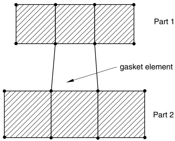
When the gaskets and their neighboring parts have matched meshes, it is straightforward to connect gaskets to other components in a model simply by sharing nodes (see Figure 32.6.3–3).
text_image
Part 1
gasket element
Part 2
Figure 32.6.3–3 Gasket elements sharing nodes with other Abaqus elements.
This method of connecting gaskets to other components is suited for cases when no frictional slip occurs between the gasket and the other components. It can be used whether or not the membrane behavior of the gasket elements is defined; however, if the gasket membrane behavior is defined, using a contact pair approach will lead to more realistic results since the difference in membrane stiffness between the gasket and its neighboring parts may lead to frictional slip. The method of sharing nodes will also lead to some small tensile stresses in the gasket should the parts connected to the gasket be pulled apart, as a result of the numerical stabilization technique added to the gasket thickness-direction behavior (see “Defining the gasket behavior directly using a gasket behavior model,” Section 32.6.6). The contact pair approach will avoid such tensile stresses. This node-sharing approach cannot be used with the gasket elements that consider only thickness-direction behavior.
# Using gasket elements that model thickness-direction behavior only
In general, the modeling techniques discussed earlier can be used with gasket elements that model thickness-direction behavior only. However, these elements have only one displacement degree of freedom per node and cannot share nodes with elements that have all displacement degrees of freedom active at a node. They can, however, share nodes with other gasket elements that model thickness-direction behavior only.