![](images/page-901_17570474c7139c8e875c4ad834d8aa9060ae58b70ec37a2952e25720349bff5a.jpg)
text_image N M L K J l i j k l m n
Nodes i, j, k, l, m, and n are specified in that order, thereby identifying a slide line progressing from i to node n. These nodes must lie on the outer tube. ITT-type elements are defined on nodes I, J, K, ... and interact with the slide line. Figure 40.3.1–1 Internal tube-to-tube contact example. # Input File Usage: \*SLIDE LINE, GENERATE first node number, last node number, increment between node numbers # Smoothing the slide line Convergence is often improved by smoothing the discontinuities in surface tangents between slide line segments, thereby providing a smoothly varying tangent along the slide line. For details about smoothing slide lines, see “Contact formulations in Abaqus/Standard,” Section 38.1.1. # Defining nondefault mechanical surface interactions with tube-to-tube contact elements By default, Abaqus/Standard uses “hard,” frictionless contact with tube-to-tube contact elements. You can assign optional mechanical surface interaction models. The following mechanical surface interaction models are available: • Friction. See “Frictional behavior,” Section 37.1.5, for details. • Modified “hard” contact, softened contact, and viscous damping. See “Contact pressure-overclosure relationships,” Section 37.1.2, and “Contact damping,” Section 37.1.3, for details. # 40.3.2 TUBE-TO-TUBE CONTACT ELEMENT LIBRARY # Product: Abaqus/Standard # References • “Tube-to-tube contact elements,” Section 40.3.1 • \*INTERFACE • \*SLIDE LINE # Overview This section provides a reference to the tube-to-tube contact elements available in Abaqus/Standard. # Element types ITT21 Tube-to-tube element for use with two-dimensional beam and pipe elements ITT31 Tube-to-tube element for use with three-dimensional beam and pipe elements Active degrees of freedom ITT21: 1, 2 ITT31: 1, 2, 3 Additional solution variables ITT21: Two additional variables relating to the contact forces. ITT31: Three additional variables relating to the contact forces. # Nodal coordinates required ITT21: X, Y ITT31: X, Y, Z # Element property definition Input File Usage: Use the following option to identify the second (outer) pipe with which the specified ITT contact elements on the first (inner) pipe can interact: \*SLIDE LINE Use the following option to give the radial clearance between the pipes as a positive number when modeling a tube sliding within another tube: \*INTERFACE When the elements are modeling contact between the exterior surfaces of two pipes, the sum of the external radii of the pipes is given as a negative number. Element-based loading None. Element output
Stress components
S11Normal component of the force between the two pipes.
S12Shear force between the two pipes, parallel to the axis of the second (outer) pipe.
S13Shear force between the two pipes, normal to the contact direction and to the axis of the second (outer) pipe (for ITT31 only).
Strain components
E11Overclosure of the surfaces in the direction normal to the tangent to the centerline of the second (outer) pipe.
E12Accumulated relative tangential motion between the two pipes, parallel to the axis of the second (outer) pipe.
E13Accumulated relative tangential motion between the two pipes, normal to the contact direction and to the axis of the second (outer) pipe (for ITT31 only).
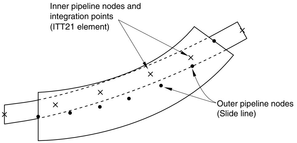
# 2D internal tube contact ![](images/page-905_ce551ef868c2328080d7baedd69f76612049b701ad154c9b9cee2e01c648df10.jpg)
text_image Inner pipeline nodes and integration points (ITT21 element) Outer pipeline nodes (Slide line)
# 2D external tube contact ![](images/page-905_8da0175628828c2df4d12ecdcd67fa591777a5498b576e200ac2470090ee7962.jpg)
text_image First pipeline nodes and integration points (ITT21 element) Second pipeline nodes (Slide line)
# 3D internal tube contact ![](images/page-906_f61b4db804c6f43db6ddaa0e83892540f7fc23f316facf4ea2974aecb671dfae.jpg)
text_image Inner pipeline nodes and integration points (ITT31 element) Outer pipeline nodes (Slide line)
# 3D external tube contact ![](images/page-906_0cd514a4361de443b6253b03907674cb2cfe79c75b9cc20c09a4534a2e931cc2.jpg)
text_image First pipeline nodes and integration points (ITT31 element) Second pipeline nodes (Slide line)
# 40.4 Slide line contact elements • “Slide line contact elements,” Section 40.4.1 • “Axisymmetric slide line element library,” Section 40.4.2 # 40.4.1 SLIDE LINE CONTACT ELEMENTS # Product: Abaqus/Standard # References • “Axisymmetric slide line element library,” Section 40.4.2 • \*INTERFACE • \*SLIDE LINE # Overview # Slide line elements: • can model the finite-sliding interaction between two deforming bodies when the sliding occurs along a line (“slide line”) that lies in a specific plane; • assume that tangential motions orthogonal to a slide line are zero or small (Abaqus/Standard treats such motions as being infinitesimal); • can be used with axisymmetric stress/displacement elements; • are recommended for specific applications, such as when a contact surface is the surface of a substructure or when CAXA or SAXA elements are involved in contact; • are available for first- and second-order elements; and • use the same “master-slave” concepts for enforcing contact constraints seen in surface-based contact. For a general discussion of contact modeling, see Chapter 36, “Defining Contact Interactions.” # Modeling contact between deformable bodies with slide lines Determining the location of the areas of contact and the surface tractions between contacting structures are common goals of Abaqus simulations (see Figure 40.4.1–1). Slide lines and slide line contact elements can provide this information for simulations where both structures are deformable and the finite sliding of the structures occurs along well-defined lines. # Local basis system for contact stresses and relative motions of the bodies Abaqus/Standard reports the contact stresses between the bodies and the relative motions of the bodies in a local basis system that is attached to the slide line surface. The local basis system is defined by the normal to the slide line, , and two orthogonal local tangent directions, and (see Figure 40.4.1–2). ![](images/page-910_be307d8d5a09a3c98137cb8aad100035eb0cb4a353c5684295687b486dfcc7f2.jpg)
text_image Contact stress (including friction) Deformable structure T Contact area
Figure 40.4.1–1 Interaction between deformable structures. ![](images/page-910_48ce287130d95179540deb55d26a84f4f69dbbce971ddf6af14cf0fca51ac3d5.jpg)
text_image T - stress transmitted between the surfaces [S11] [S12] [S13] n t₂ t₁
Figure 40.4.1–2 Local system for interface contact normal and shear traction.