| SS LINEAR | Constrain a shell node to a solid node line for linear elements (S4, S4R, S4R5, C3D8, C3D8R, SAX1, CAX4, etc.). |
| SS BILINEAR(S) | Constrain a shell node to a solid node line for edge lines on quadratic elements (S8R, S8R5, C3D20, C3D20R, SAX2, CAX8, etc.). |
| SSF BILINEAR(S) | Constrain a midside node of a quadratic shell element (S8R, S8R5) to midface lines on 20-node bricks (C3D20, C3D20R, etc.). |
# Modeling a shell-to-solid element transition
The SLIDER, SS LINEAR, SS BILINEAR, and SSF BILINEAR MPCs allow for a transition from shell element modeling to solid element modeling on a shell surface. This modeling technique can be used to obtain solutions at shell-solid intersections or other discontinuities, where the local modeling should use full three-dimensional theory but the other parts of the structure can be modeled as shells. The shellto-solid submodeling capability (“Submodeling: overview,” Section 10.2.1) and the surface-based shellto-solid coupling constraint (“Shell-to-solid coupling,” Section 35.3.3) can also be used to obtain more accurate solutions in such cases, with considerably less modeling effort.
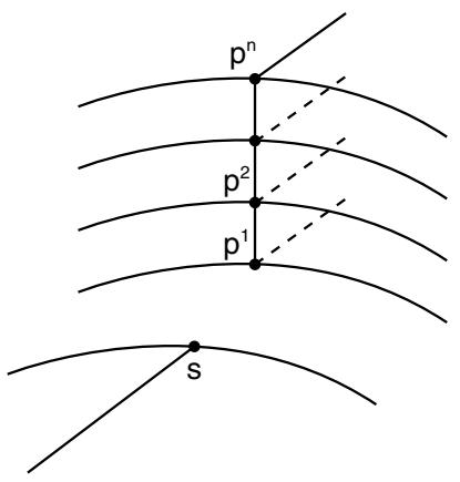
In Abaqus/Standard the MPC usage assumes that the interface between the shell and solid elements is a surface containing the normals to the shell along the line of intersection of the meshes, so that the lines of nodes on the solid mesh side of the interface in the normal direction to the surface are straight lines. (Line $a , p ^ { 1 } , p ^ { 2 } , . . . , b$ in Figure 35.2.2–14 and lines $p ^ { 1 } , p ^ { 2 } , . . . , p ^ { n }$ in Figure 35.2.2–19 to Figure 35.2.2–20 should be straight lines.) It also assumes that the nodes of the solid elements are spaced uniformly on the interface surface as indicated in Figure 35.2.2–14 and Figure 35.2.2–19 to Figure 35.2.2–20. For each shell node on the edge use MPC type SS LINEAR, SS BILINEAR, or SSF BILINEAR, as appropriate, to constrain the shell node to the corresponding line or face of solid element nodes through the thickness. Then, use a SLIDER MPC to constrain each interior node on the line through the thickness to remain on the straight line defined by the bottom and top nodes of that line. For an example, see “Multi-point constraints,” Section 5.1.17 of the Abaqus Verification Guide.
The SS BILINEAR and SSF BILINEAR MPCs are not intended for use with the variable node solid elements (C3D27, C3D27H, C3D27R, and C3D27RH).
In Abaqus/Standard MPCs SS LINEAR, SS BILINEAR, and SSF BILINEAR eliminate all displacement components and two of the rotation components at the shell node, and the SLIDER MPC eliminates two displacement components at each interior solid element node in the interface. Therefore, any boundary conditions needed at the interface (such as those required when the shell/solid interface intersects a symmetry plane) should be applied only to the top and bottom nodes on the solid element side of the interface.
# Using MPC type SS LINEAR
MPC type SS LINEAR constrains a shell corner node to a line of edge nodes on solid elements for linear elements (S4, S4R, or S4R5; C3D8, C3D8R; SAX1; CAX4; etc.).
The constrained nodes need not lie exactly on these lines, but it is suggested that they be in close proximity to the lines for meaningful results.