# 단부자유도 해제조건(Beam End Release)이 고려되었을 때의 강성역
기둥 및 거더부재의 어느 한쪽 또는 양쪽 연결점이 핀접합에 의해 자유도해제조건이 부여되었을 때 해당 연결점에 대해서도 강성역을 고려합니다.
# 기둥부재의 강성역 고려방법
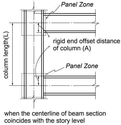
기둥부재의 강성역은 기둥의 상단과 하단부에서 각각 계산하게 됩니다.(그림 1.6.12 참조)
기둥부재와 거더부재의 연결부에서 기둥부재의 강단이력거리는 연결되는거더부재의 춤(Depth)과 방향에 의해 결정되며 그림 1.6.15에서와 같이 기둥부재와 보부재가 연결될 경우, 기둥부재의 강단이력거리는 요소좌표계 y축과 z축방향 각각에 대해 산정됩니다.
기둥부재에 여러 방향으로부터 거더부재가 접합될 경우, 각 방향별 강성역의 산정방법은 다음과 같습니다. (그림 1.6.16 참조)
$$
R C _ {y} = B D \times \cos^ {2} \theta \quad R C _ {z} = B D \times \sin^ {2} \theta
$$
RCy : 기둥부재 상부의 요소좌표계 y축 방향에 대한 강성역
RC : 기둥부재 상부의 요소좌표계 z축 방향에 대한 강성역
BD:(Depth)
θ : 기둥부재의 요소좌표계 z축과 거더부재가 이루는 각도
기둥부재의 각 방향별 강성역은 기둥부재에 연결된 거더부재들에 대해 각방향별 강성역을 구한 다음, 그 중 가장 큰 값으로 결정합니다.
column centerline axis (parallel with the z-axis)
text_image
Panel Zone
rigid end offset distance
of column (A)
Panel Zone
column length(L)
when the centerline of beam section
coincides with the story level
column centerline axis (parallel with the z-axis)
text_image
Panel Zone
rigid end offset
distance of
column (A)
Panel Zone
when the top of beam is flush with
the story level
(a) 기둥부재의 강성역
text_image
column centerline axis
column centerline axis
column member
beam member
column member
Panel Zone
Panel Zone
B
clear length of beam
A
length between nodes (L)
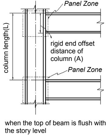
(b) 보부재의 강성역
Offset Factor
effective length for stiffness calculation
1.00
L-1.00×(A+B)
0.75
L-0.75×(A+B)
0.50
L-0.50×(A+B)
0.25
L-0.25×(A+B)
0.00
L-0.00×(A+B)
Offset Factor: rigid end offset factor entered in “Panel Zone Effects”
(c) 강성고려길이 (기둥의 경우 B=0)
그림 1.6.12 Panel Zone Effects 기능을 사용하여 강단이격거리를 고려할 때
요소의 휨/전단강성의 계산에 사용되는 길이
text_image
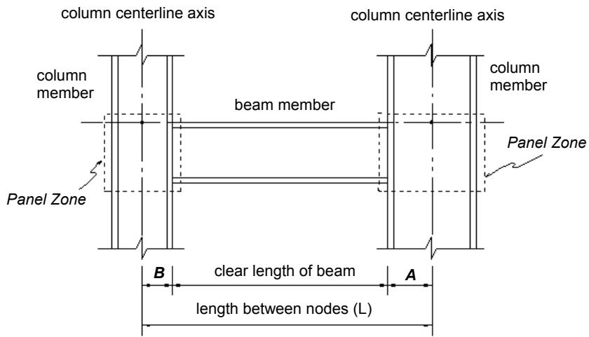
rigid end offset location at i-th node
rigid end offset location at j-th node
distributed load on beam element
i-end
L₁
L₁ (length for shear/bending stiffness calculation)
L
j-end
L
zone in which load is converted into shear force only at i-th node
zone in which load is converted into both shear and moment
zone in which load is converted into shear force only at j-end
V₃
V₁
V₂
V₄
M₁
M₂
locations for member force output(▼)
" " " " "
Li = 1.0 Ri : “Panel Zone”is selected for the locations of member force output
Li=ZF Ri : “Offset Position”is selected for the locations of member force output
Lj = 1.0 Rj : “Panel Zone”is selected for the locations of member force output
Lj=ZF Rj : “Offset Position”is selected for the locations of member force output
Ri : rigid end offset distance at i-th node
Rj : rigid end offset distance at j-th node
ZF : rigid end Offset Factor
V1, V2 : shear forces due to distributed load between the offset ends
M1, M2 : moments due to distributed load between the offset ends
V3, V4 : shear forces due to distributed load between the offset ends and the nodal points
(a) 보부재
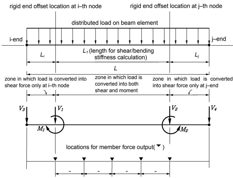
그림 1.6.13 Panel Zone Effects 기능을 사용하여 강성역을 고려할 때
분포하중의 고려방법 및 부재력 출력위치
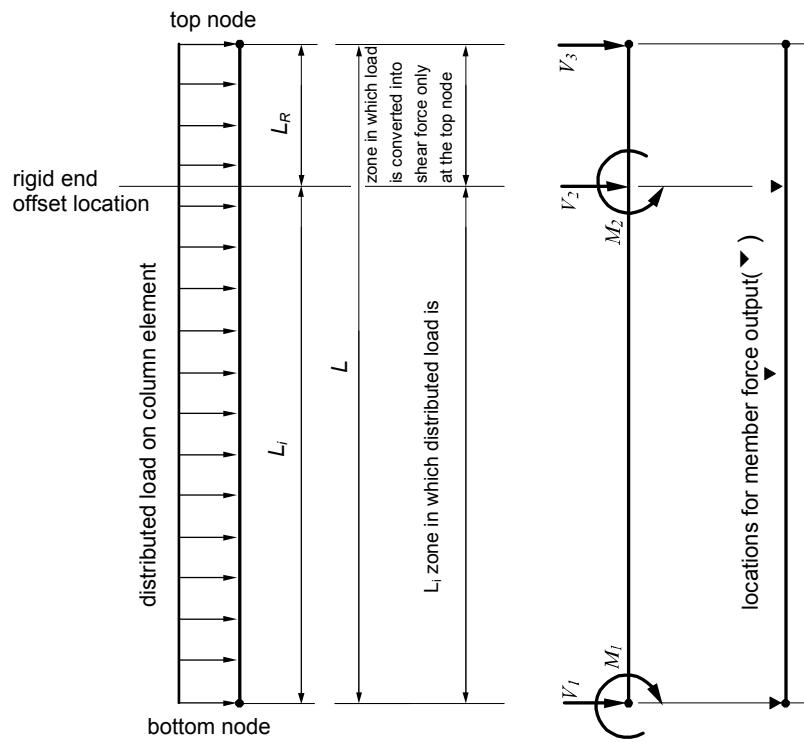
text_image
top node
L_R
zone in which load
is converted into
shear force only
at the top node
rigid end
offset location
distributed load on column element
L_1
L
L1 zone in which distributed load is
bottom node
V_3
V_2
M_2
locations for member force output( )
V_1
M_1
LR=1.0R “Panel Zone” is selected for the location of member force output
LR=ZFR “Offset Position”is selected for the locations of member force output Where R is the rigid end offset factor
V1, V2 shear forces due to distributed load between the offset end and the bottomnode
M1, M2 :moments due to distributed load between the offset end and the bottom node
V3 : shear force due to distributed load between the offset end and the top node
(b) 기둥부재
그림 1.6.14 Panel Zone Effects 기능을 사용하여 강성역을 고려할 때
분포하중의 고려방법 및 부재력 출력위치
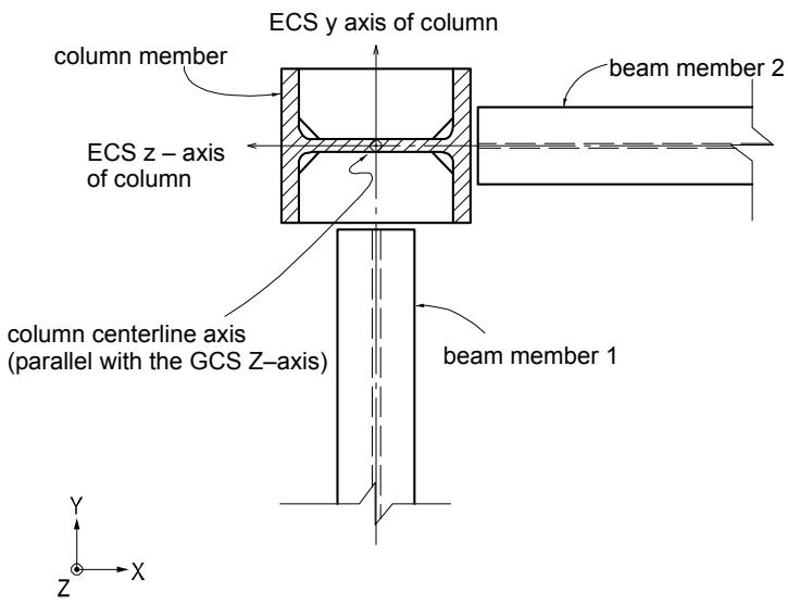
text_image
ECS y axis of column
column member
ECS z - axis
of column
beam member 2
column centerline axis
(parallel with the GCS Z-axis)
beam member 1
Y
Z
X
(a) 평면도
text_image
column centerline axis
beam member 2
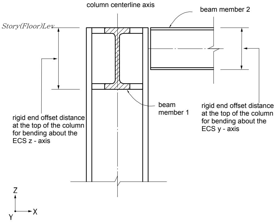
Story(Floor)Lev
rigid end offset distance
at the top of the column
for bending about the
ECS z - axis
beam member 1
rigid end offset distance
at the top of the column
for bending about the
ECS y - axis
Z
Y
X
(b) 정면도
그림 1.6.15 Panel Zone Effect 기능을 사용할 경우, 기둥 부재의 강성역
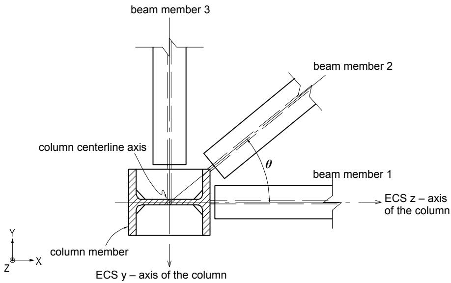
text_image
beam member 3
column centerline axis
column member
column member
Y
Z
X
Y
Z
X
column centerline axis
beam member 2
beam member 1
ECS z - axis of the column
θ
ECS y - axis of the column
beam member1: BD = 250 $\theta = 0^{\circ}$ $RC_{z} = 250 \times \sin^{2}0^{\circ} = 0.0$ $RC_{y} = \cos^{2}0^{\circ} = 250.0$
beam member2: BD = 200 $\theta = 40^{\circ}$ $RC_{z} = 200 \times \sin^{2} 40^{\circ} = 82.6$ $RC_{y} = 200 \times \cos^{2} 0^{\circ} = 117.4$
beam member3: BD = 150 $\theta = 90^{\circ}$ $RC_{z} = 150 \times \sin^{2} 90^{\circ} = 150$ $RC_{y} = 150 \times \cos^{2} 90^{\circ} = 0.0$
rigid end offset distance of the column: $RC_y = \mathrm{MAX}(250.0, 117.4, 0.0) = 250.0$
$$
R C _ {z} = \mathrm{MAX} (0. 0, 8 2. 6, 1 5 0. 0) = 1 5 0. 0
$$
where, BD : beam depth
RCz : rigid end offset distance for bending about the minor axis
RCy : rigid end offset distance for bending about the major axis
그림 1.6.16 Panel Zone Effects 기능을 사용할 경우, 기둥부재의 강성역 산정 예
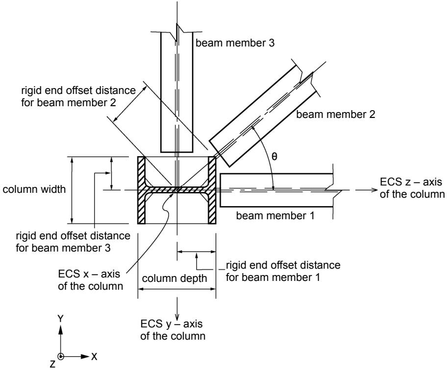
# 거더부재의 강성역 고려방법
거더부재의 강성역은 거더부재 양 끝단에 대한 기둥부재의 높이(Depth)과폭(Width)에 의해 결정되며 산정식은 다음과 같다.
\- 각 방향별 강단이격거리에 의한 이격거리 산정식 (그림 1.6.17 참조)
$$
R B = \frac {\text { Depth } \times \cos^ {2} \theta}{2} + \frac {\text { Width } \times \sin^ {2} \theta}{2}
$$
Depth : 기둥부재의 요소좌표계 z축 방향의 단면길이
Width : 기둥부재의 요소좌표계 y축 방향의 단면길이
text_image
beam member 3
rigid end offset distance
for beam member 2
beam member 2
column width
θ
ECS z – axis
of the column
beam member 1
rigid end offset distance
for beam member 3
ECS x – axis
of the column
column depth
rigid end offset distance
for beam member 1
ECS y – axis
of the column
Y
Z
X
그림 1.6.17 Panel Zone Effects 기능을 사용할 경우, 거더부재의 강단이격거리
text_image
beam member
ECS z - axis
of column
θ
ECS x - axis
of beam
column centerline at i– th node
column centerline at j– th node
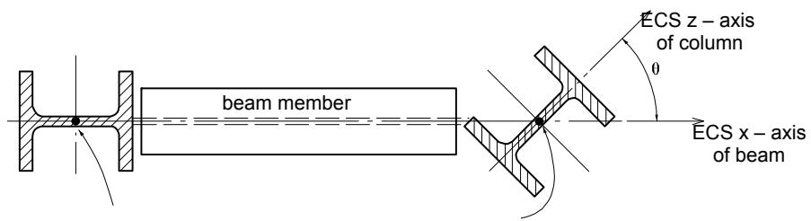
150, 100depth of column section = width of column section= , for $\theta = 4 0 ^ { \circ }$
150 0 100 0 2 2cos sin rigid end offset distance at i-th node = $: \frac { 1 5 0 \times { c o s } ^ { 2 } 0 ^ { \circ } } { 2 } + \frac { 1 0 0 \times { s i n } ^ { 2 } 0 ^ { \circ } } { 2 } = 7 5 . 0$
150 40 1002cos rigid end offset distance at j-th node = 40 2 sin ${ \mathsf { n o d e } } = { \frac { 1 5 0 \times c o s ^ { 2 } 4 0 ^ { \circ } } { 2 } } + { \frac { 1 0 0 \times s i n ^ { 2 } 4 0 ^ { \circ } } { 2 } } = 6 4 . 7$
그림 1.6.18 Panel Zone Effects 기능을 사용할 경우, 거더부재의 강성역 산정 예
# 6-9-2 Beam End Offsets 기능을 이용하여 보요소의 양단에 강성역을직접 입력하는 방법
Beam End Offsets에서는 다음의 2가지 방법으로 보요소의 양단에 강성역 거리를직접 입력하게 됩니다.
1. 양절점에서의 이격거리(Offset Length)를 전체좌표계 기준으로 X, Y, Z축방향의 성분거리로 입력
2. 양절점에서의 이격거리를 요소좌표계 x축 방향의 거리로 입력
첫째 방법은 접합부의 방향별 편심거리를 입력합니다. 요소강성을 계산하거나 분포하중 또는 자중을 계산할 때 고려되는 거리는 이격된 양절점 사이의 전길이가고려됩니다. 그리고 부재력의 출력위치 또는 단부자유도해제조건에 대해서도 이격된 위치를 기준으로 조정됩니다. (그림 1.6.11 (b), (c) 참조)
둘째 방법은 축방향의 편심거리를 입력합니다. 이 방법은 요소강성의 계산과 부재력의 출력위치 또는 단부자유도해제조건에 대해서는 Panel Zone Effects 기능에서“Panel Zone" 을 선택하고 강성역 보정계수를 1.0을 입력한 경우와 같은 효과를가지나, 분포하중에 대해서는 조정된 거리 대신 양절점 사이의 전체길이를 사용합니다.
# 6-10 주절점과 종속절점(강체연결기능)
강체연결기능(Boundary탭>Link그룹>Rigid Link)은 구조물의 기하학적 상대거동을 상호 구속하는 기능입니다.
기하학적 상대거동의 구속은 임의 절점의 자유도에 한 개 또는 그 이상의 절점의 자유도를 종속시킴으로써 이루어지며 여기서 임의 절점을 주절점(Master Node)이라 하고 자유도가 종속되는 절점을 종속절점(slave node)이라 합니다.
강체연결기능에는 다음과 같이 네 가지 종류가 있습니다.
Rigid Body Connection
Rigid Plane Connection
Rigid Translation Connection
Rigid Rotation Connection
Rigid Body Connection은 주절점과 종속절점들이 3차원 강체로 연결된 것처럼 상호거동이 구속되는 방법으로, 각 절점간의 거리가 일정하게 유지되며 상호구속방정식은 다음과 같습니다.
$$
U _ {X s} = U _ {X m} + R _ {Y m} \Delta Z - R _ {Z m} \Delta Y
$$
$$
U _ {Y s} = U _ {Y m} + R _ {Z m} \Delta X - R _ {X m} \Delta Z
$$
$$
U _ {Z s} = U _ {Z m} + R _ {X m} \Delta Y - R _ {Y m} \Delta X
$$
$$
R _ {X s} = R _ {X m}
$$
$$
R _ {Y s} = R _ {Y m}
$$
$$
R _ {Z s} = R _ {Z m}
$$
여기서, $\Delta X = X_{m} - X_{s}$ , $\Delta Y = Y_{m} - Y_{s}$ , $\Delta Z = Z_{m} - Z_{s}$
상기 식에서 첨자 m과 s는 각각 주절점과 종속절점을 의미하며, $U_{X}$ , $U_{Y}$ , $U_{Z}$ 는 각각 전체좌표계 기준의 X방향변위, Y방향변위, Z방향변위 성분을, 그리고 $R_{X}$ , $R_{Y}$ , $R_{Z}$ 는 각각 전체좌표계 기준의 X방향에 대한 회전변위, Y방향에 대한 회전변위, Z방향에 대한 회전변위 성분을 의미합니다. 그리고 $X_{m}$ , $Y_{m}$ , $Z_{m}$ 는 주절점의 좌표를