# Specified Temperatures
In addition to convection and radiation boundary conditions, nodal point temperature conditions may also be specified. These boundary conditions can be incorporated in the same way as known nodal point displacements are prescribed in stress analysis.
A common procedure is to substitute the known nodal point temperatures in the heat flow equilibrium equations (7.21) and (7.28) and delete the corresponding equations from those to be solved (see Section 4.2.2). However, an effective way to impose nodal point temperatures can be the procedure that is employed to impose convection boundary conditions. Namely, by assigning a very large value of convection coefficient h, where h is much larger than the conductivity of the material, the surface nodal point temperature will be equal to the prescribed environmental nodal point temperature.
EXAMPLE 7.4: Establish the governing finite element equations for the analysis of the infinite parallel-sided slab shown in Fig. E7.2 but neglect the radiation effects. Use the modified Newton-Raphson solution and only one parabolic one-dimensional element to model the slab. (In practice, depending on the temperature gradient to be predicted by the analysis, many more elements may be needed.)
The governing equations for this problem are obtained from (7.28),
$$
\left(^ {t} \mathbf {K} ^ {k} + ^ {t} \mathbf {K} ^ {c}\right) \Delta \boldsymbol {\theta} ^ {(i)} = ^ {t + \Delta t} \mathbf {Q} + ^ {t + \Delta t} \mathbf {Q} ^ {c (i - 1)} - ^ {t + \Delta t} \mathbf {Q} ^ {k (i - 1)} \tag {a}
$$
where
$$
^ {t} \mathbf {K} ^ {k} = \int_ {V} \mathbf {B} ^ {T} {} ^ {t} k \mathbf {B} d V
$$
$$
^ \prime \mathbf {K} ^ {c} = \int_ {S _ {c}} ^ {\prime} h \mathbf {H} ^ {S ^ {T}} \mathbf {H} ^ {S} d S
$$
$$
{ } ^ { t + \Delta t } \mathbf { Q } ^ { c ( i - 1 ) } = \int _ { S _ { c } } { } ^ { t + \Delta t } h ^ { ( i - 1 ) } \mathbf { H } ^ { S ^ { T } } \left[ \mathbf { H } ^ { S } ( { } ^ { t + \Delta t } \boldsymbol { \theta } _ { e } - { } ^ { t + \Delta t } \boldsymbol { \theta } ^ { ( i - 1 ) } ) \right] d S
$$
$$
{ } ^ { t + \Delta t } \mathbf { Q } ^ { k ( i - 1 ) } = \int _ { V } \mathbf { B } ^ { T } \left[ { } ^ { t + \Delta t } k ^ { ( i - 1 ) } \mathbf { B } ^ { t + \Delta t } \boldsymbol { \theta } ^ { ( i - 1 ) } \right] d V
$$
$$
{ } ^ { t + \Delta t } \mathbf { Q } ^ { T } = [ 0 \quad q ^ { S } \quad 0 ]
$$
and
$$
\Delta \boldsymbol {\theta} ^ {(i) ^ {T}} = \left[ \begin{array}{c c c} \Delta \theta_ {1} ^ {(i)} & \Delta \theta_ {2} ^ {(i)} & \Delta \theta_ {3} ^ {(i)} \end{array} \right]
$$
$$
{ } ^ { t + \Delta t } \boldsymbol { \theta } ^ { ( i - 1 ) ^ { T } } = \left[ \begin{array} { c c c } t + \Delta t \theta _ { 1 } ^ { ( i - 1 ) } & t + \Delta t \theta _ { 2 } ^ { ( i - 1 ) } & t + \Delta t \theta _ { 3 } ^ { ( i - 1 ) } \end{array} \right]
$$
$$
^ {t + \Delta t} \boldsymbol {\theta} _ {e} ^ {T} = [ 2 0 \quad 0 \quad 0 ]
$$
For the one-dimensional parabolic element, we use the interpolation functions $h_{1}$ , $h_{2}$ , and $h_{3}$ in Fig. 5.3 to construct H,
$$
\mathbf {H} = \left[ \frac {1}{2} r (1 + r) - \frac {1}{2} r (1 - r) (1 - r ^ {2}) \right]
$$
and $H^{s}$ corresponding to node 1 is equal to H evaluated at $r = +1$ ,
$$
\mathbf {H} ^ {s} = \left[ \begin{array}{c c c} 1 & 0 & 0 \end{array} \right]
$$
We also have $J = L / 2$ ; hence,
$$
\mathbf {B} = \frac {2}{L} \left[ \frac {1}{2} (1 + 2 r) - \frac {1}{2} (1 - 2 r) - 2 r \right]
$$
Also, the conductivity of the material is given by, for example, for time t,
$$
^ \prime k = 1 0 + 2 \sum_ {i = 1} ^ {3} h _ {i} ^ {\prime} \theta_ {i}
$$
and similarly for the convection coefficient we have
$$
\left. ^ {\prime} h \right| _ {r = + 1} = 2 + ^ {\prime} \theta_ {1}
$$
With these quantities defined we can now evaluate all matrices in (a) and perform the temperature analysis. Note that we are using $S_{c} = 1$ and $V = 1 \times L$ .
See Exercise 7.6 for the analysis including the radiation effects.
# Transient Analysis
As mentioned earlier, in transient heat transfer analysis the heat capacity effects are included in the analysis as part of the rate of heat generated. The equations considered in the solution depend, however, on whether implicit or explicit time integration is used, just as in structural analysis (see Chapter 9 and, for example, K. J. Bathe and M. R. Khoshgoftaar [A]).
If the Euler backward implicit time integration is employed, the heat flow equilibrium equations used are obtained directly from the equations governing steady-state conditions [see (7.18)]. Namely, using for element m,
$$
\dot {\boldsymbol {\theta}} ^ {(m)} (x, y, z, t) = \mathbf {H} ^ {(m)} (x, y, z) \dot {\boldsymbol {\theta}} (t) \tag {7.30}
$$
and now using (7.12), we have in (7.28),
$$
{ } ^ { t + \Delta t } \mathbf { Q } _ { B } = \sum _ { m } \int _ { V ^ { ( m ) } } \mathbf { H } ^ { ( m ) T } ( { } ^ { t + \Delta t } q ^ { B ( m ) } - { } ^ { t + \Delta t } ( \rho c ) ^ { ( m ) } \mathbf { H } ^ { ( m ) } { } ^ { t + \Delta t } \dot { \mathbf { \theta } } ) d V ^ { ( m ) } \tag {7.31}
$$
where $t+\Delta t q^{B(m)}$ no longer includes the rate at which heat is stored within the material. Hence, the finite element heat flow equilibrium equations considered in transient conditions are, in linear analysis,
$$
\mathbf {C} ^ {t + \Delta t} \dot {\boldsymbol {\theta}} + (\mathbf {K} ^ {k} + \mathbf {K} ^ {c}) ^ {t + \Delta t} \boldsymbol {\theta} = ^ {t + \Delta t} \mathbf {Q} + ^ {t + \Delta t} \mathbf {Q} ^ {e} \tag {7.32}
$$
and in nonlinear analysis (using the full Newton-Raphson iteration but without linearizing the heat capacity effect, see Section 9.6),
$$
\begin{array}{l} { } ^ { t + \Delta t } \mathbf { C } ^ { ( i ) } { } ^ { t + \Delta t } \dot { \boldsymbol { \theta } } ^ { ( i ) } + \left( { } ^ { t + \Delta t } \mathbf { K } ^ { k ( i - 1 ) } + { } ^ { t + \Delta t } \mathbf { K } ^ { c ( i - 1 ) } + { } ^ { t + \Delta t } \mathbf { K } ^ { r ( i - 1 ) } \right) \Delta \boldsymbol { \theta } ^ { ( i ) } \tag {7.33} \\ = ^ {t + \Delta t} \mathbf {Q} + ^ {t + \Delta t} \mathbf {Q} ^ {c (i - 1)} + ^ {t + \Delta t} \mathbf {Q} ^ {r (i - 1)} - ^ {t + \Delta t} \mathbf {Q} ^ {k (i - 1)} \\ \end{array}
$$
where $\mathbf{C},{}^{t + \Delta t}\mathbf{C}^{(i)}$ are the heat capacity matrices,
$$
\mathbf {C} = \sum_ {m} \int_ {V ^ {(m)}} \mathbf {H} ^ {(m) ^ {T}} \rho c ^ {(m)} \mathbf {H} ^ {(m)} d V ^ {(m)}
$$
$$
{ } ^ { t + \Delta t } \mathbf { C } ^ { ( i ) } = \sum _ { m } \int _ { V ^ { ( m ) } } \mathbf { H } ^ { ( m ) ^ { T } } { } ^ { t + \Delta t } ( \rho c ) ^ { ( m ) ^ { ( i ) } } \mathbf { H } ^ { ( m ) } d V ^ { ( m ) } \tag {7.34}
$$
The matrices defined in $(7.34)$ are consistent heat capacity matrices because the same element interpolations are employed for the temperatures as for the time derivatives of temperatures. Following the concepts of displacement analysis, it is also possible to use a lumped heat capacity matrix and lumped heat flow input vector, which are evaluated by simply lumping heat capacities and heat flow inputs, using appropriate contributory areas, to the element nodes (see Section 4.2.4).
If, on the other hand, the Euler forward explicit time integration is used, the solution for the unknown temperatures at time $t + \Delta t$ is obtained by considering heat flow equilibrium at time t. Applying the relation in (7.7) at time t and substituting the finite element interpolations for temperatures, temperature gradients, and time derivatives of temperatures, we obtain in linear and nonlinear analysis, respectively,
$$
\mathbf {C} ^ {\prime} \dot {\boldsymbol {\theta}} = ^ {\prime} \mathbf {Q} + ^ {\prime} \mathbf {Q} ^ {c} - ^ {\prime} \mathbf {Q} ^ {k} \tag {7.35}
$$
$$
^ \prime \mathbf {C} ^ {\prime} \dot {\boldsymbol {\theta}} = ^ {\prime} \mathbf {Q} + ^ {\prime} \mathbf {Q} ^ {c} + ^ {\prime} \mathbf {Q} ^ {r} - ^ {\prime} \mathbf {Q} ^ {k} \tag {7.36}
$$
where the nodal point heat flow input vectors on the right of (7.35) and (7.36) are defined in Table 7.2 [but the superscript $(i - 1)$ is not used and $t + \Delta t$ is replaced by t). The solution using explicit time integration is effective only when a lumped heat capacity matrix is employed.
In closing this section we recall that we did not include in the above formulations the effects of phase changes and latent heat generation and of bodies radiating onto each other. These effects can be included in the analysis as briefly described in the following examples. We discuss the solution of the governing equations as a function of time in Section 9.6.
EXAMPLE 7.5: Consider that the slab shown in Fig. E7.2 is initially at a temperature $\theta_{i}$ and that $\theta_{i}$ is below the phase change temperature $\theta_{ph}$ . The heating of the slab will result in traversing $\theta_{ph}$ and hence in a phase change. Assume that the slab is a pure substance with latent heat l per unit mass and a constant mass density of $\rho$ and specific heat capacity c. Show how the latent heat effect can be included in the transient analysis of the slab.
In this problem solution, the following boundary conditions must be satisfied at the phase transition interface $S_{ph}$ ,
$$
\left. \begin{array}{c} \theta = \theta_ {\mathrm{ph}} \\ \Delta q ^ {s} d S = - \rho l \frac {d V}{d t} \end{array} \right\} \quad \text { on } S _ {\mathrm{ph}} \tag {a}
$$
where dV/dt is the rate of volume currently converted on $S_{ph}$ . The relations in (a) state that at the interface separating the two phases heat is absorbed at a rate proportional to the volumetric rate of conversion of the material.
In this case a transient analysis is required. We use the simple three-node element idealization with a lumped heat capacity matrix (for a unit cross section),
$$
\mathbf {C} = \left[ \begin{array}{c c c} \rho c \frac {L}{4} & & \\ & \rho c \frac {L}{2} & \\ & & \rho c \frac {L}{4} \end{array} \right] \tag {b}
$$
We also choose to use the Euler backward time integration scheme (see Section 9.6 for details), with a constant time step $\Delta t$ , in which
$$
{ } ^ { t + \Delta t } \dot { \boldsymbol { \theta } } ^ { ( i ) } = \frac { { } ^ { t + \Delta t } \boldsymbol { \theta } ^ { ( i ) } - { } ^ { t } \boldsymbol { \theta } } { \Delta t } = \frac { \boldsymbol { \theta } ^ { ( i ) } } { \Delta t } \tag {c}
$$
Using (b) and (c) with the given initial condition and the matrices defined in Example 7.4, a transient analysis not including latent heat effects can be performed directly.
However, to introduce the interface conditions in (a), we calculate for each nodal point a "latent heat contribution." This results in the vector $\mathbf{H}_l$ ,
$$
\mathbf {H} _ {l} = \left[ \begin{array}{l} \rho l \frac {L}{4} \\ \rho l \frac {L}{2} \\ \rho l \frac {L}{4} \end{array} \right] \tag {d}
$$
Let us call $H_{l,total,k}$ the entry in $H_{l}$ corresponding to nodal point k. The transient analysis including the latent heat effects can then be performed as follows.
As long as $r^{+ \Delta t} \theta_k^{(i)}$ as calculated by the usual step-by-step solution is smaller than $\theta_{\mathrm{ph}}$ , no considerations for latent heat enter the solution.
However, consider that at the start of a new step $^{t}\theta_{k} + \Delta \theta_{k}^{(1)} = ^{t + \Delta t}\theta_{k}^{(1)} \geq \theta_{\mathrm{ph}}$ and that with the adjustment for latent heat given below, the "projected" (but not accepted) increments in nodal temperatures are $\Delta \theta_{k}^{(i)} > 0$ . Then we calculate for the first step traversing the phase change:
$$
\tilde {\theta} _ {k} = \theta_ {\mathrm{ph}} - ^ {\prime} \theta_ {k} \tag {e}
$$
$$
\Delta Q _ {l, k} ^ {(1)} = \int_ {v _ {k}} \frac {1}{\Delta t} \rho c \left(\Delta \theta_ {k} ^ {(1)} - \tilde {\theta} _ {k}\right) d V
$$
$$
\Delta Q _ {l, k} ^ {(i)} = \int_ {v _ {k}} \frac {1}{\Delta t} \rho c \Delta \theta_ {k} ^ {(i)} d V; \quad i = 2, 3, \dots
$$
for all subsequent steps and iterations transversing the phase change:
$$
\Delta Q _ {l, k} ^ {(i)} = \int_ {V _ {k}} \frac {1}{\Delta t} \rho c \Delta \theta_ {k} ^ {(i)} d V; \quad i = 1, 2, 3, \dots
$$
where the volume integration is performed over the volume $V_{k}$ associated with the finite element node k, until
$$
\sum_ {\substack {\text {steps}, \\ \text {iterations}}} \Delta Q _ {l, k} ^ {(i)} \Delta t = H _ {l, \text {total}, k} \tag{f}
$$
In the last iteration only a portion of the value of $\Delta Q_{l,k}^{(i)}\Delta t$ may be used to reach $H_{l,\text{total},k}$ .
The solution procedure is based on the condition that as long as a value $\Delta Q_{l,k}^{(i)}$ is applicable, the temperature increment at node k is given only by the $\tilde{\theta}_{k}$ defined in (e) rather than by the usual sum of all $\Delta\theta_{k}^{(i)}$ . These temperature increments are added as usual to the current temperatures only after condition (f) has been fulfilled. Hence, in essence the temperature increase at a node is constrained to the phase change temperature $\theta_{ph}$ until $H_{l,total,k}$ has been supplied to the node. The same concept is used when the phase change occurs during cooling and when a nonpure substance is being considered (in which case the temperature during the phase change is not constant). More details on this solution approach are given by W. D. Rolph, III, and K. J. Bathe [A].
EXAMPLE 7.6: Consider the two slabs shown in Fig. E7.6 radiating on each other. Assume gray diffuse surface radiation. Formulate the problem of heat flow between the slabs.

text_image
L = 10
s
r
Temperature θ₁
1
n₁
α₁
S₁
z₁
y₁
x₁
h
Emissivities
ε₁ = ε₂
S₂
r
α₂
2
y₂
z₂
x₂
L = 10
Slab 2
Temperature θ₂
10
10
text_image
Prescribed heat flow
input q^S per unit area
L
L
Prescribed temperature θ_e
Very long column,
thermal conductivity k
text_image
θθ = 20
Uniform convection
with coefficient h = 4 + θ
∞
L = 10
θS = 100
∞
Conductivity k = 60 + θ
text_image
Node 1
Heat generated
per unit volume = q^B
4
6
Material properties
k, p, c, h
10
3
4
1
14
Face exposed to convection,
environmental temperature θ_e
4-node element in
axisymmetric conditions
text_image
s
θ₁
4
r
6
text_image
100°F
4 in
Conductivity k
0°F
0°F
0°F
4 in
Infinitely long column
text_image
Suddenly a surface
temperature of -45°F
is applied and kept constant
Slab is initially at 0°F
| Problem | Variable θ | Constants $k_x, k_y, k_z$ | Input $q^B$ | Input $q^S$ |
| Heat transfer | Temperature | Thermal conductivity | Internal heat generation | Prescribed heat flow |
| Seepage | Total head | Permeability | Internal flow generation | Prescribed flow condition |
| Torsion | Stress function | $(Shear modulus)^{-1}$ | 2 × (Angle of twist) | — |
| Inviscid incompressible irrotational flow | Potential function | 1 | Source or sink | Prescribed velocity |
| Electric conduction | Voltage | Electric conductivity | Internal current source | Prescribed current |
| Electrostatic field analysis | Field potential | Permittivity | Charge density | Prescribed field |
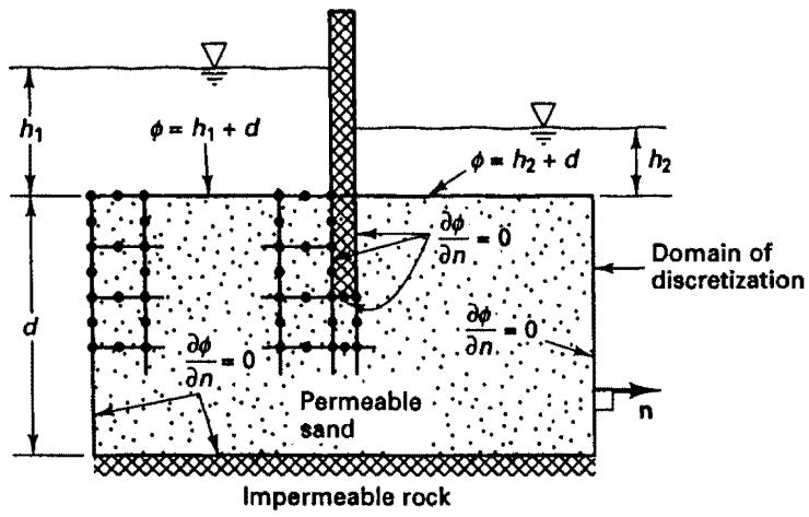