Load ID (*DLOAD)Abaqus/CAE Load/InteractionUnitsDescription
P2Line load $FL^{-1}$ Force per unit length in beam local 2-direction.
P1NULine load $FL^{-1}$ Nonuniform force per unit length in beam local 1-direction with magnitude supplied via user subroutine DLOAD in Abaqus/Standard and VDLOAD in Abaqus/Explicit. (Only for beams in space.)
P2NULine load $FL^{-1}$ Nonuniform force per unit length in beam local 2-direction with magnitude supplied via user subroutine DLOAD in Abaqus/Standard and VDLOAD in Abaqus/Explicit.
$ROTA^{(S)}$ Rotational body force $T^{-2}$ Rotary acceleration load (magnitude is input as $\alpha$ , where $\alpha$ is the rotary acceleration).
$ROTDYNF^{(S)}$ Not supported $T^{-1}$ Rotordynamic load (magnitude is input as $\omega$ , where $\omega$ is the angular velocity).
The following load types are available only for PIPE elements:
Load ID (*DLOAD)Abaqus/CAE Load/InteractionUnitsDescription
HPIPipe pressure $FL^{-2}$ Hydrostatic internal pressure (closed-end condition), varying linearly with the global Z-coordinate.
HPEPipe pressure $FL^{-2}$ Hydrostatic external pressure (closed-end condition), varying linearly with the global Z-coordinate.
PIPipe pressure $FL^{-2}$ Uniform internal pressure (closed-end condition).
PEPipe pressure $FL^{-2}$ Uniform external pressure (closed-end condition).
Load ID(*DLOAD)Abaqus/CAELoad/InteractionUnitsDescription
PENUPipe pressure $FL^{-2}$ Nonuniform external pressure (closed-end condition) with magnitude supplied via user subroutine DLOAD.
PINUPipe pressure $FL^{-2}$ Nonuniform internal pressure (closed-end condition) with magnitude supplied via user subroutine DLOAD.
# Abaqus/Aqua loads Abaqus/Aqua loads are specified as described in “Abaqus/Aqua analysis,” Section 6.11.1. They are not available for open-section beams and do not apply to beams that are defined to have additional inertia due to immersion in fluid (see “Additional inertia due to immersion in fluid” in “Beam section behavior,” Section 29.3.5). In Abaqus/Explicit, Aqua loads can be applied only on linear beam and pipe elements.
Load ID(*CLOAD/*DLOAD)Abaqus/CAELoad/InteractionUnitsDescription
$FDD^{(A)}$ Not supported $FL^{-1}$ Transverse fluid drag load.
$FD1^{(A)}$ Not supportedFFluid drag force on the first end of the beam (node 1).
$FD2^{(A)}$ Not supportedFFluid drag force on the second end of the beam (node 2 or node 3).
$FDT^{(A)}$ Not supported $FL^{-1}$ Tangential fluid drag load.
$FI^{(A)}$ Not supported $FL^{-1}$ Transverse fluid inertia load.
$FI1^{(A)}$ Not supportedFFluid inertia force on the first end of the beam (node 1).
$FI2^{(A)}$ Not supportedFFluid inertia force on the second end of the beam (node 2 or node 3).
$PB^{(A)}$ Not supported $FL^{-1}$ Buoyancy load (closed-end condition).
$WDD^{(A)}$ Not supported $FL^{-1}$ Transverse wind drag load.
$WD1^{(A)}$ Not supportedFWind drag force on the first end of the beam (node 1).
Load ID(*CLOAD/*DLOAD)Abaqus/CAELoad/InteractionUnitsDescription
WD2(A)Not supportedFWind drag force on the second end of the beam (node 2 or node 3).
# Foundations Foundations are available only in Abaqus/Standard and are specified as described in “Element foundations,” Section 2.2.2.
Load ID(*FOUNDATION)Abaqus/CAE Load/InteractionUnitsDescription
$FX^{(S)}$ Not supported $FL^{-2}$ Stiffness per unit length in global X-direction.
$FY^{(S)}$ Not supported $FL^{-2}$ Stiffness per unit length in global Y-direction.
$FZ^{(S)}$ Not supported $FL^{-2}$ Stiffness per unit length in global Z-direction (only for beams in space).
$F1^{(S)}$ Not supported $FL^{-2}$ Stiffness per unit length in beam local 1-direction (only for beams in space).
$F2^{(S)}$ Not supported $FL^{-2}$ Stiffness per unit length in beam local 2-direction.
# Surface-based loading # Distributed loads Surface-based distributed loads are specified as described in “Distributed loads,” Section 34.4.3.
Load ID(*DSLOAD)Abaqus/CAELoad/InteractionUnitsDescription
PPressure $FL^{-1}$ Force per unit length in beam local 2-direction. The distributed surface force is positive in the direction opposite to the surface normal.
PNUPressure $FL^{-1}$ Nonuniform force per unit length in beam local 2-direction with magnitude supplied via user subroutine DLOAD in
Load ID (\*DSLOAD) Abaqus/CAE Load/Interaction Units Description Abaqus/Standard and VDLOAD in Abaqus/Explicit. The distributed surface force is positive in the direction opposite to the surface normal. # Incident wave loading Incident wave loading is also available for these elements, with some restrictions. See “Acoustic and shock loads,” Section 34.4.6. # Element output See “Beam cross-section library,” Section 29.3.9, for a description of the beam element output locations. # Stress, strain, and other tensor components Stress and other tensors (including strain tensors) are available for elements with displacement degrees of freedom. All tensors, except for meshed sections, have the same components. For example, the stress components are as follows: S11 Axial stress. S22 Hoop stress (available only for pipe elements). S33 Radial stress (available only for thick-walled pipe elements). S12 Shear stress caused by torsion (available only for beam-type elements in space). This component is not available when thin-walled, open sections are employed (I-section, L-section, and arbitrary open section). # Stress and strain for section points for meshed sections S11 Axial stress. S12 Shear stress along the second cross-section axis caused by shear force and, for beam elements in space, torsion. S13 Shear stress along the first cross-section axis caused by shear force and torsion (available only for beams in space). # Section forces, moments, and transverse shear forces SF1 Axial force. SF2 Transverse shear force in the local 2-direction (not available for B23, B23H, B33, B33H). SF3 Transverse shear force in the local 1-direction (available only for beams in space, not available for B33, B33H).
SM1Bending moment about the local 1-axis.
SM2Bending moment about the local 2-axis (available only for beams in space).
SM3Twisting moment about the beam axis (available only for beams in space).
BIMOMBimoment due to warping (available only for open-section beams in space).
ESF1Effective axial force for beams subjected to pressure loading (available for all Abaqus/Standard stress/displacement analysis types except response spectrum and random response).
See “Beam element formulation,” Section 3.5.2 of the Abaqus Theory Guide, for the definitions of the section forces and moments. The effective axial section force for beams subjected to pressure loading is defined as $$ \mathrm{ESF1} = \mathrm{SF1} + p _ {e} A _ {e} - p _ {i} A _ {i}, $$ where $p _ { e }$ and $p _ { i }$ are the external and the internal pressures, respectively, and $A _ { e }$ and $A _ { i }$ are the external and the internal pipe areas as defined in the load definition. The pressure loadings (with a closedend condition) that are relevant to the effective axial force are external/internal pressure (load types PE, PI, PENU, and PINU); external/internal hydrostatic pressure (load types HPE and HPI); and, in an Abaqus/Aqua environment, buoyancy pressure, PB, which includes dynamic pressure if waves are present. For beams that are not subjected to pressure loading, the effective axial force ESF1 is equal to the usual axial force SF1. Section strains, curvatures, and transverse shear strains
SE1Axial strain.
SE2Transverse shear strain in the local 2-direction (not available for B23, B23H, B33, and B33H).
SE3Transverse shear strain in the local 1-direction (available only for beams in space, not available for B33 and B33H).
SK1Curvature change about the local 1-axis.
SK2Curvature change about the local 2-axis (available only for beams in space).
SK3Twist of the beam (available only for beams in space).
BICURVBicurvature due to warping (available only for open-section beams in space).
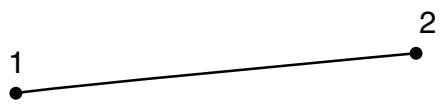
# Node ordering on elements ![](images/page-346_cb808658dc2ebb343d608c4451bd575fb6e79b47b4ac7a0eb99e01f43e0f73b3.jpg)
natural_image Simple line segment connecting two numbered points (no text or symbols)
2 - node element ![](images/page-346_bddea42bc345f44fb823104f739b6ad778a18ddb233d6fe10443b41433bb617c.jpg)
text_image 1 2 3
3 - node element For beams in space an additional node may be given after a beam element’s connectivity (in the element definition—see “Element definition,” Section 2.2.1) to define the approximate direction of the first crosssection axis, . See “Beam element cross-section orientation,” Section 29.3.4, for details. # Numbering of integration points for output ![](images/page-346_9de825bdf550f8fa8ae3150359a8efe165982135933dd70d3bf2e4d3c3b8b953.jpg)
text_image 1 × 1 2
2 - node element ![](images/page-346_a16e589910e4eec3608603122b5d48f54a192cb1c3880fb36e735528cbe2d641.jpg)
text_image 1 1 2 2 3
3 - node quadratic element ![](images/page-346_236ce6e2b3e8b6b9801ade5bca1da2877090d13a799740cb1a2e097621bd4cbc.jpg)
flowchart ```mermaid graph TD 1 -->|1| 2 2 -->|2| 3 3 -->|3| 2 ```
2 - node cubic element # 29.3.9 BEAM CROSS-SECTION LIBRARY Products: Abaqus/Standard Abaqus/Explicit Abaqus/CAE # References • “Beam modeling: overview,” Section 29.3.1 • “Choosing a beam cross-section,” Section 29.3.2 • “Frame elements,” Section 29.4.1 • “Defining profiles,” Section 12.2.2 of the Abaqus/CAE User’s Guide # Overview This section describes the standard beam sections that are available in Abaqus/Standard and Abaqus/Explicit for use with beam elements. A subset of the standard beam sections are available for use with frame elements in Abaqus/Standard. General (nonstandard) beam cross-sections can be defined as described in “Choosing a beam cross-section,” Section 29.3.2. # Arbitrary, thin-walled, open and closed sections ![](images/page-347_30db94fc5cdcf7aa21b7c5534d5d0ce512ca8ffbd8bbfe028344ce85c6448646.jpg)
text_image A 1 t_AB 2 B 3 4 5 t_BC C 6 t_CD 7 D 1 2
Example of arbitrary section The arbitrary section type is provided to permit modeling of simple, arbitrary, thin-walled, open and closed sections. You specify the section by defining a series of points in the thin-walled cross-section of the beam; these points are then linked by straight line segments, each of which is integrated numerically along the axis of the section so that the section can be used together with nonlinear material behavior. An independent thickness is associated with each of the segments making up the arbitrary section. Warping effects are included when an arbitrary section is used with open-section beam elements (available only in Abaqus/Standard). Input File Usage: Use either of the following options: \*BEAM SECTION, SECTION=ARBITRARY \*BEAM GENERAL SECTION, SECTION=ARBITRARY Abaqus/CAE Usage: Property module: Create Profile: Arbitrary # Restrictions • An arbitrary section can be used only with beams in space (three-dimensional models). • An arbitrary section should not be used to define closed sections with branches, multiply connected closed sections, or open sections with disconnected regions. • For each individual segment of an arbitrary section there is no bending stiffness about the line joining the end points of the segment. Thus, an arbitrary section cannot be made up of only one segment. # Geometric input data First, give the number of segments, the local coordinates of points A and B, and the thickness of the segment connecting these two vertices. Then, proceed by giving the local coordinates of point C and the thickness of the segment between points B and C, followed by the local coordinates of point D and the thickness of the segment between points C and D, and so on. An arbitrary section can contain as many segments as needed. All coordinates of section definition points are given in the local 1–2 axis system of the section. The origin of the local 1–2 axis system is the beam node, and the position of this node used to define the section is arbitrary: it does not have to be the centroid. # Defining a closed section A closed section is defined by making the starting and end points coincident. Only single-cell closed sections can be modeled accurately. Closed sections with fins (single branches attached to the cell) cannot be modeled with the capability in Abaqus. # Defining an arbitrary section with discontinuous branches If the arbitrary section contains discontinuous sections (branches), a section with zero thickness should be used to return from the ending point of the branch to the starting point of the subsequent section. This zero thickness section should always coincide with a nonzero thickness section. For an example of an I-section defined using this method, see “Buckling analysis of beams,” Section 1.2.1 of the Abaqus Benchmarks Guide. # Default integration A three-point Simpson integration scheme is used for each segment making up the section. For more detailed integration, specify several segments along each straight portion of the section. # Default stress output points if a beam section integrated during the analysis is used The vertices of the section. # Temperature and field variable input at specific points through beam sections integrated during the analysis Give the value at each vertex of the section (points A, B, C, D in the figure). # Box section Input File Usage: Use one of the following options: \*BEAM SECTION, SECTION=BOX \*BEAM GENERAL SECTION, SECTION=BOX \*FRAME SECTION, SECTION=BOX Abaqus/CAE Usage: Property module: Create Profile: Box ![](images/page-349_1610d8e36a0d9c31d102f7ed35292040f7b3fe0c3dc66f7d1297d6fc82090649.jpg)
text_image 2 5 4 t1 t2 b 3 2 t3 t4 1 a 5 4 1 3 2 1
Default integration, beam in a plane ![](images/page-349_f5680c8dc3ff9e997518217b6b2f6d56aa9bc2efb4f6e5f660dc8eb26b4a0817.jpg)
text_image 2 8 7 6 9 10 t2 t1 4 b 11 t3 t4 3 1 12 13 14 15 16 a 2 1
Default integration, beam in space # Geometric input data $$ \textbf {a}, \textbf {b}, t _ {1}, t _ {2}, t _ {3}, t _ {4} $$ # Default integration (Simpson) Beam in a plane: 5 points Beam in space: 5 points in each wall (16 total) # Nondefault integration input for a beam section integrated during the analysis Beam in a plane: Give the number of points in each wall that is parallel to the 2-axis. This number must be odd and greater than or equal to three. Beam in space: Give the number of points in each wall that is parallel to the 2-axis, then the number of points in each wall that is parallel to the 1-axis. Both numbers must be odd and greater than or equal to three. # Default stress output points if a beam section integrated during the analysis is used Beam in a plane: Bottom and top (points 1 and 5 above for default integration). Beam in space: 4 corners (points 1, 5, 9, and 13 above for default integration). # Temperature and field variable input at specific points for beam sections integrated during the analysis Give the value at each of the points shown below. ![](images/page-350_c7bac92ef9eb4cdedd1ad0c8f08139aa5d89ab5c0bed89e1e6d852073eeab60f.jpg)
text_image 2 3 2 1 2 1
Beam in a plane ![](images/page-350_054aae4fe15934d4330c2d2da3431bc2acf31ac87725c47e360a7e29bd637e10.jpg)
text_image 2 3 2 4 1
Beam in space # Temperature input for a frame section Constant temperature throughout the element cross-section is assumed; therefore, only one temperature value per node is required. # Circular section Input File Usage: Use one of the following options: \*BEAM SECTION, SECTION=CIRC \*BEAM GENERAL SECTION, SECTION=CIRC \*FRAME SECTION, SECTION=CIRC Abaqus/CAE Usage: Property module: Create Profile: Circular