| Load ID(*DLOAD) | Abaqus/CAE Load/Interaction | Units | Description |
| $\text{ROTA}^{(S)}$ | Not supported | $T^{-2}$ | Rotary acceleration load (magnitude is input as $\alpha$ , where $\alpha$ is the rotary acceleration). |
| $\text{ROTDYNF}^{(S)}$ | Not supported | $T^{-1}$ | Rotordynamic load (magnitude is input as $\omega$ , where $\omega$ is the angular velocity). |
Element output
ELKE Element kinetic energy (available only from Abaqus/Standard).
Nodes associated with the element
1 node.
# 30.3 Rigid elements
• “Rigid elements,” Section 30.3.1
• “Rigid element library,” Section 30.3.2
# 30.3.1 RIGID ELEMENTS
Products: Abaqus/Standard Abaqus/Explicit Abaqus/CAE
# References
• “Rigid body definition,” Section 2.4.1
• “Rigid element library,” Section 30.3.2
• \*RIGID BODY
• “Defining rigid body constraints,” Section 15.15.2 of the Abaqus/CAE User’s Guide, in the HTML version of this guide
# Overview
Rigid elements:
• can be used to define the surfaces of rigid bodies for contact;
• can be used to define rigid bodies for multibody dynamic simulations;
• can be attached to deformable elements;
• can be used to constrain parts of a model;
• are used to apply Abaqus/Aqua loads to rigid structures; and
• are associated with a given rigid body and share a common node known as the rigid body reference node.
# Choosing an appropriate element
Use R2D2 elements in plane strain or plane stress analysis, RAX2 elements in axisymmetric planar geometries, and R3D3 and R3D4 elements in three-dimensional analysis.
RB2D2 and RB3D2 elements are often used in Abaqus/Standard to model offshore structures that will transmit Abaqus/Aqua loads but will not deform. They can also be used as rigid links between nodes on deformable bodies.
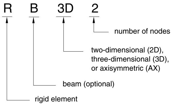
# Naming convention
Rigid elements in Abaqus are named as follows: