| MAXECRT | Maximum value of the nominal strain damage initiation criterion at a material point during the analysis. It is evaluated as $\max\{\frac{\langle\varepsilon_n\rangle}{\varepsilon_n^o},\frac{\varepsilon_s}{\varepsilon_s^o},\frac{\varepsilon_t}{\varepsilon_t^o}\}$ . |
| MMIXDME | Mode mix ratio during damage evolution. It is evaluated as $1 - m_1$ . In general, it varies with time at a given integration point. This variable is set to $-1.0$ before initiation of damage. |
| MMIXDMI | Mode mix ratio at damage initiation. It is evaluated as $1 - m_1$ at the time of damage initiation at an integration point for the very first time. It remains constant with time at a given integration point. This variable is set to $-1.0$ before initiation of damage. |
| QUADSCRT | Maximum value of the quadratic nominal stress damage initiation criterion at a material point during the analysis. It is evaluated as $(\frac{\langle t_n\rangle}{t_n^o})^2 + (\frac{t_s}{t_s^o})^2 + (\frac{t_t}{t_t^o})^2$ . |
| QUADECRT | Maximum value of the quadratic nominal strain damage initiation criterion at a material point during the analysis. It is evaluated as $(\frac{\langle\varepsilon_n\rangle}{\varepsilon_n^o})^2 + (\frac{\varepsilon_s}{\varepsilon_s^o})^2 + (\frac{\varepsilon_t}{\varepsilon_t^o})^2$ . |
| ALLCD | The approximate amount of energy over the whole model or over an element set that is associated with viscous regularization in Abaqus/Standard. Corresponding output variables (such as CENER, ELCD, and ECDDEN) represent the energy associated with viscous regularization at the integration point level and element level (the last quantity represents the energy per unit volume in the element), respectively. |
For the variables above that indicate whether a certain damage initiation criterion has been satisfied or not, a value that is less than 1.0 indicates that the criterion has not been satisfied, while a value of 1.0 or higher indicates that the criterion has been satisfied. If damage evolution is specified for this criterion, the maximum value of this variable does not exceed 1.0. However, if damage evolution is not specified for the initiation criterion, this variable can have values higher than 1.0. The extent to which the variable is higher than 1.0 may be considered to be a measure of the extent to which this criterion has been violated.
# Additional references
• Benzeggagh, M. L., and M. Kenane, “Measurement of Mixed-Mode Delamination Fracture Toughness of Unidirectional Glass/Epoxy Composites with Mixed-Mode Bending Apparatus,” Composites Science and Technology, vol. 56, pp. 439–449, 1996.
• Camanho, P. P., and C. G. Davila, “Mixed-Mode Decohesion Finite Elements for the Simulation of Delamination in Composite Materials,” NASA/TM-2002–211737, pp. 1–37, 2002.
# 32.5.7 DEFINING THE CONSTITUTIVE RESPONSE OF FLUID WITHIN THE COHESIVE ELEMENT GAP
Products: Abaqus/Standard Abaqus/CAE
# References
• “Cohesive elements: overview,” Section 32.5.1
• “Defining the constitutive response of cohesive elements using a traction-separation description,” Section 32.5.6
• \*FLUID LEAKOFF
• \*GAP FLOW
• Chapter 21, “Adhesive joints and bonded interfaces,” of the Abaqus/CAE User’s Guide
# Overview
The cohesive element fluid flow model:
• is typically used in geotechnical applications, where fluid flow continuity within the gap and through the interface must be maintained;
• enables fluid pressure on the cohesive element surface to contribute to its mechanical behavior, which enables the modeling of hydraulically driven fracture;
• enables modeling of an additional resistance layer on the surface of the cohesive element; and
• can be used only in conjunction with traction-separation behavior.
The features described in this section are used to model fluid flow within and across surfaces of pore pressure cohesive elements.
# Defining pore fluid flow properties
The fluid constitutive response comprises:
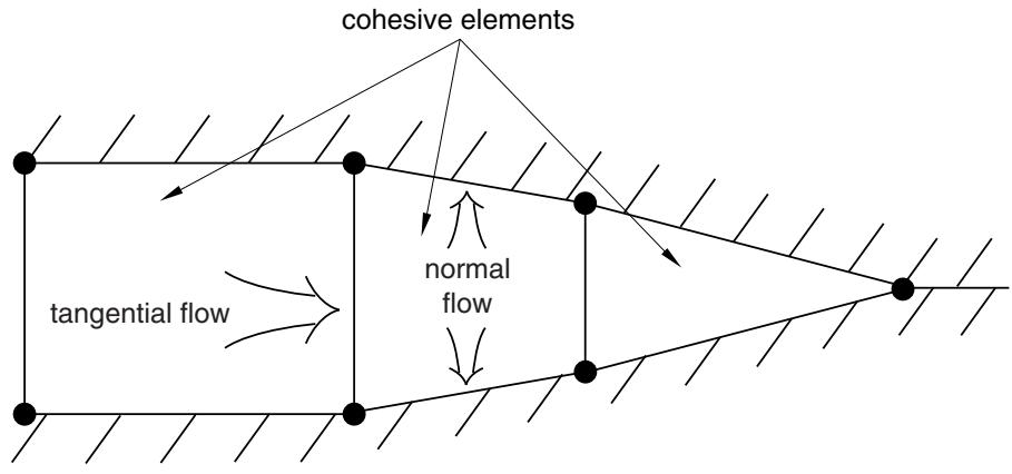
• Tangential flow within the gap, which can be modeled with either a Newtonian or power law model; and
• Normal flow across the gap, which can reflect resistance due to caking or fouling effects.
The flow patterns of the pore fluid in the element are shown in Figure 32.5.8–1. The fluid is assumed to be incompressible, and the formulation is based on a statement of flow continuity that considers tangential and normal flow and the rate of opening of the cohesive element.
# Specifying the fluid flow properties
You can assign tangential and normal flow properties separately.