| Input File Usage: | You must identify the node set for which the local transformed system is defined. |
| *TRANSFORM, NSET=name |
| Abaqus/CAE Usage: | In Abaqus/CAE you define a local coordinate system independent of its use and then refer to it when you apply a load or boundary condition at a node. |
| Any module:Tools→Datum:Type:CSYS |
| Interaction module: load or boundary condition editor:CSYS:Edit:select local coordinate system |
# Defining a local coordinate system in a model that contains an assembly of part instances
In a model defined in terms of an assembly of part instances, you can define a nodal transformation at the part, part instance, or assembly level. A nodal transformation defined at the part or part instance level will be rotated according to the positioning data given for each instance of that part (or for the part instance). See “Defining an assembly,” Section 2.10.1. Multiple transformation definitions are not allowed at a node, even if one of them is at the part level and another is at the assembly level.
# Large-displacement analysis
The transformed coordinate system is always a set of fixed Cartesian axes at a node (even for cylindrical or spherical transforms). These transformed directions are fixed in space; the directions do not rotate as the node moves. Therefore, even in large-displacement analysis, the displacement components must always be given with respect to these fixed directions in space.
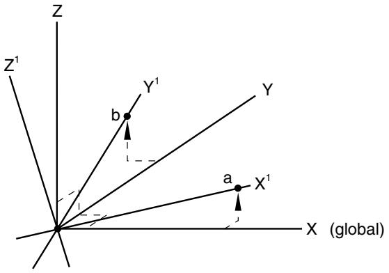
# Defining a rectangular Cartesian coordinate transformation
In a rectangular Cartesian transformation the transformed directions are parallel at all nodes of the set. The coordinates of two points must be given, as shown in Figure 2.1.5–1.