database,” Section 4.1.3) or for contour integral output. If you specify an output frequency of 0 for the history output to the output database, contour integral values will not be written to the output database.
Input File Usage: \*CONTOUR INTEGRAL, CRACK NAME=crack name, CONTOURS=n, FREQUENCY=f
Abaqus/CAE Usage: Step module: history output request editor: Domain: Crack: crack name, Number of contours: n, Save output at
# 11.4.3 CRACK PROPAGATION ANALYSIS
Products: Abaqus/Standard Abaqus/Explicit Abaqus/CAE
# References
• “Defining an analysis,” Section 6.1.2
• “Fracture mechanics: overview,” Section 11.4.1
• “Low-cycle fatigue analysis using the direct cyclic approach,” Section 6.2.7
• “Surface-based cohesive behavior,” Section 37.1.10
• \*COHESIVE BEHAVIOR
• \*CONTACT CLEARANCE
• \*DEBOND
• \*DIRECT CYCLIC
• \*FRACTURE CRITERION
• \*NODAL ENERGY RATE
• “Defining surface-to-surface contact in an Abaqus/Standard analysis” in “Defining surface-tosurface contact,” Section 15.13.7 of the Abaqus/CAE User’s Guide
# Overview
Crack propagation analysis:
• allows for six types of fracture criteria in Abaqus/Standard—critical stress at a certain distance ahead of the crack tip, critical crack opening displacement, crack length versus time, VCCT (the Virtual Crack Closure Technique), enhanced VCCT, and the low-cycle fatigue criterion based on the Paris law;
• allows for the VCCT fracture criterion in Abaqus/Explicit;
• in Abaqus/Standard models quasi-static crack growth in two dimensions (planar and axisymmetric) for all types of fracture criteria and in three dimensions (solid, shells, and continuum shells) for VCCT, enhanced VCCT, and the low-cycle fatigue criteria; and
• in Abaqus/Explicit models crack growth in three dimensions (solid, shells, and continuum shells) for VCCT criterion; and
• requires that you define two distinct initially bonded contact surfaces between which the crack will propagate.
# Defining initially bonded crack surfaces in Abaqus/Standard
Potential crack surfaces are modeled as slave and master contact surfaces (see “Defining contact pairs in Abaqus/Standard,” Section 36.3.1). Any contact formulation except the finite-sliding, surface-to-surface formulation can be used. The predetermined crack surfaces are assumed to be initially partially bonded
so that the crack tips can be identified explicitly by Abaqus/Standard. Initially bonded crack surfaces cannot be used with self-contact.
Define an initial condition to identify which part of the crack is initially bonded. You specify the slave surface, the master surface, and a node set that identifies the initially bonded part of the slave surface. The unbonded portion of the slave surface will behave as a regular contact surface. Either the slave surface or the master surface must be specified; if only the master surface is given, all of the slave surfaces associated with this master surface that have nodes in the node set will be bonded at these nodes.
If a node set is not specified, the initial contact conditions will apply to the entire contact pair; in this case, no crack tips can be identified, and the bonded surfaces cannot separate.
If a node set is specified, the initial conditions apply only to the slave nodes in the node set. Abaqus/Standard checks to ensure that the node set defined includes only slave nodes belonging to the contact pair specified.
By default, the nodes in the node set are considered to be initially bonded in all directions.
Input File Usage: \*INITIAL CONDITIONS, TYPE=CONTACT
Abaqus/CAE Usage: Interaction module: Create Interaction: Surface-to-surface contact (Standard)
# Bonding only in the normal direction
For fracture criteria based on the critical stress, critical crack opening displacement, or crack length versus time, it is possible to bond the nodes in the node set (or the contact pair if a node set is not defined) only in the normal direction. In this case the nodes are allowed to move freely tangential to the contact surfaces. Friction (“Frictional behavior,” Section 37.1.5) cannot be specified if the nodes are bonded only in the normal direction.
Bonding only in the normal direction is typically used to model bonded contact conditions in Mode I crack problems where the shear stress ahead of the crack along the crack plane is zero.
Input File Usage: \*INITIAL CONDITIONS, TYPE=CONTACT, NORMAL
Abaqus/CAE Usage: Bonding only in the normal direction is not supported in Abaqus/CAE.
# Activating the crack propagation capability in Abaqus/Standard
The crack propagation capability must be activated within the step definition to specify that crack propagation may occur between the two surfaces that are initially partially bonded. You specify the surfaces along which the crack propagates.
If the crack propagation capability is not activated for partially bonded surfaces, the surfaces will not separate; in this case the specified initial contact conditions would have the same effect as that provided by the tied contact capability, which generates a permanent bond between two surfaces during the entire analysis (see “Defining tied contact in Abaqus/Standard,” Section 36.3.7).
Input File Usage: \*DEBOND, SLAVE=slave\_surface\_name, MASTER=master\_surface\_name
Abaqus/CAE Usage: Interaction module: Create Interaction: Surface-to-surface contact (Standard), select master and slave surfaces
# Propagation of multiple cracks
Cracks can propagate from either a single crack tip or multiple crack tips. The crack propagation capability in Abaqus/Standard requires that the surfaces be initially partially bonded so that the crack tips can be identified. A contact pair can have crack propagation from multiple crack tips. However, only one crack propagation criterion is allowed for a given contact pair. Crack propagation along several contact pairs can be modeled by specifying multiple crack propagation definitions.
# Defining and activating crack propagation in Abaqus/Explicit
In Abaqus/Explicit potential crack surfaces are modeled as bonded general contact surfaces (see “Defining general contact interactions in Abaqus/Explicit,” Section 36.4.1) in the context of surface-based cohesive behavior (see “Surface-based cohesive behavior,” Section 37.1.10). Hence, the capability is available in three-dimensional analyses only and is implemented using a pure master-slave formulation. As is the case in Abaqus/Standard, the predetermined crack surfaces are assumed to be initially partially bonded so that the crack tips can be identified explicitly.
To identify which pair of surfaces determine the crack and which part of the crack is initially bonded, you must define and assign a contact clearance (see “Controlling initial contact status for general contact in Abaqus/Explicit,” Section 36.4.4). You first define a contact clearance to specify the node set that is initially bonded, and then you assign this contact clearance to a pair of two single-sided surfaces that define the crack. The unbonded portion behaves as a regular contact surface. The nodes in the node set are considered to be initially bonded in all directions.
The crack tip is identified only from the specified two surfaces and the node set. No attempt is made to determine a crack tip from all surfaces included in the general contact domain. Consequently, to be able to identify the crack tip, the surface including the specified node set must extend past the node set. Otherwise, the surfaces will not debond, and the crack cannot propagate.
You complete the definition of the crack propagation capability by defining a fracture-based cohesive behavior surface interaction. You activate the crack propagation by assigning it to the pair of surfaces that are initially partially bonded. If the fracture criterion is met, crack propagation occurs between these two surfaces. Cohesive behavior is also used to specify the elastic behavior of the bonds (see “Surface-based cohesive behavior,” Section 37.1.10).
If a fracture-based surface interaction is not assigned to a pair of surfaces, the crack definition is incomplete. Unlike Abaqus/Standard where the identified nodes will stay bonded if the crack is not activated, in Abaqus/Explicit the nodes identified by the contact clearance definition will separate without generating any interface stress.
Similar to Abaqus/Standard, cracks can propagate from single or multiple crack tips for the same pair of surfaces.
Input File Usage: Use the following options:
```sql
*CONTACT CLEARANCE, NAME=clearance_name,
SEARCH NSET=bonded_nset_name
**
*SURFACE INTERACTION, NAME=interaction_name
```
\*COHESIVE BEHAVIOR
\*FRACTURE CRITERION
..\*\*
\*CONTACT
\*CONTACT CLEARANCE ASSIGNMENT
slave\_surface, master\_surface, clearance\_name
\*CONTACT PROPERTY ASSIGNMENT
slave\_surface, master\_surface, interaction\_name
Abaqus/CAE Usage: Defining and activating crack propagation in Abaqus/Explicitis not supported in Abaqus/CAE.
# Specifying a fracture criterion
You can specify the crack propagation criteria, as discussed below. Table 11.4.3–1 shows which criteria are supported by Abaqus/Standard and Abaqus/Explicit. Only one crack propagation criterion is allowed per contact pair even if multiple cracks are present.
Table 11.4.3–1
Crack propagation criterion
Abaqus/Standard
Abaqus/Explicit
Critical stress
Yes
No
Critical crack opening displacement
Yes
No
Crack length versus time
Yes
No
VCCT
Yes
Yes
Enhanced VCCT
Yes
No
Low-cycle fatigue
Yes
No
Crack propagation analysis is carried out on a nodal basis. The crack-tip node debonds when the fracture criterion, $f ,$ reaches the value 1.0 within a given tolerance:
$$
f _ {L L} \leq f \leq f _ {U L},
$$
where $f _ { U L } = 1 + f _ { t o l }$ and $f _ { L L } ~ = ~ 1$ for VCCT, enhanced VCCT, and low-cycle fatigue criteria or $f _ { L L } = 1 - f _ { t o l }$ for other fracture criteria. You can specify the tolerance $f _ { t o l }$ . In Abaqus/Standard, if $f > 1 + f _ { t o l }$ , the time increment is cut back such that the crack propagation criterion is satisfied except in the case of an unstable crack growth problem where multiple nodes at and ahead of a crack tip are allowed to debond without the cut back of increment size in one increment. The default value of $f _ { t o l }$ is 0.1 for the critical stress, critical crack opening displacement, and crack length versus time criteria and is 0.2 for the VCCT, enhanced VCCT, and low-cycle fatigue criteria.
Input File Usage: \*FRACTURE CRITERION, TOLERANCE= , TYPE=type
Abaqus/CAE Usage: Interaction module: Create Interaction Property: Contact, Mechanical→Fracture Criterion, Type: VCCT or Enhanced VCCT, Tolerance
# Critical stress criterion
This criterion is available only in Abaqus/Standard.
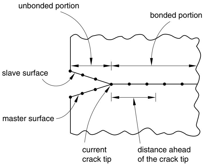
If you specify a critical stress criterion at a critical distance ahead of the crack tip, the crack-tip node debonds when the local stress across the interface at a specified distance ahead of the crack tip reaches a critical value.
This criterion is typically used for crack propagation in brittle materials. The critical stress criterion is defined as
$$
f = \sqrt {\left(\frac {\hat {\sigma} _ {n}}{\sigma^ {f}}\right) ^ {2} + \left(\frac {\tau_ {1}}{\tau_ {1} ^ {f}}\right) ^ {2} + \left(\frac {\tau_ {2}}{\tau_ {2} ^ {f}}\right) ^ {2}}, \quad \hat {\sigma} _ {n} = \max (\sigma_ {n}, 0),
$$
where $\sigma _ { n }$ is the normal component of stress carried across the interface at the distance specified; $\tau _ { 1 }$ and $\tau _ { 2 }$ are the shear stress components in the interface; and $\sigma ^ { f }$ and $\tau _ { 1 } ^ { f }$ are the normal and shear failure stresses, which you must specify. The second component of the shear failure stress, $\tau _ { 2 }$ , is not relevant in a two-dimensional analysis; therefore, the value of $\dot { \cdot } _ { 2 } f$ need not be specified. The crack-tip node debonds when the fracture criterion, $f ,$ reaches the value 1.0.
If the value of $\tau _ { 1 } ^ { f }$ is not given or is specified as zero, it will be taken to be a very large number so that the shear stress has no effect on the fracture criterion.
The distance ahead of the crack tip is measured along the slave surface, as shown in Figure 11.4.3–1. The stresses at the specified distance ahead of the crack tip are obtained by interpolating the values at the adjacent nodes. The interpolation depends on whether first-order or second-order elements are used to define the slave surface.
$\begin{array} { r l r } { \mathrm { { i n p u t \ F i l e \ U s a g e : } } \quad } & { } & { \mathrm { { * F R A C T U R E \ C R I T E R I O N , \mathrm { T Y P E = C R I T I C A L \ S T R E S S , D I S T A N C E = } } } } \end{array}$
Abaqus/CAE Usage: The critical stress criterion is not supported in Abaqus/CAE.
# Critical crack opening displacement criterion
This criterion is available only in Abaqus/Standard.
If you base the crack propagation analysis on the crack opening displacement criterion, the crack-tip node debonds when the crack opening displacement at a specified distance behind the crack tip reaches a critical value. This criterion is typically used for crack propagation in ductile materials.
The crack opening displacement criterion is defined as
$$
f = \frac {\delta}{\delta_ {c}},
$$
text_image
unbonded portion
bonded portion
slave surface
master surface
current crack tip
distance ahead of the crack tip
Figure 11.4.3–1 Distance specification for the critical stress criterion.
where is the measured value of crack opening displacement and $\delta _ { c }$ is the critical value of the crack opening displacement (user-specified). The crack-tip node debonds when the fracture criterion reaches the value 1.0.
You must supply the crack opening displacement versus cumulative crack length data. In Abaqus/Standard the cumulative crack length is defined as the distance between the initial crack tip and the current crack tip measured along the slave surface in the current configuration. The crack opening displacement is defined as the normal distance separating the two faces of the crack at the given distance.
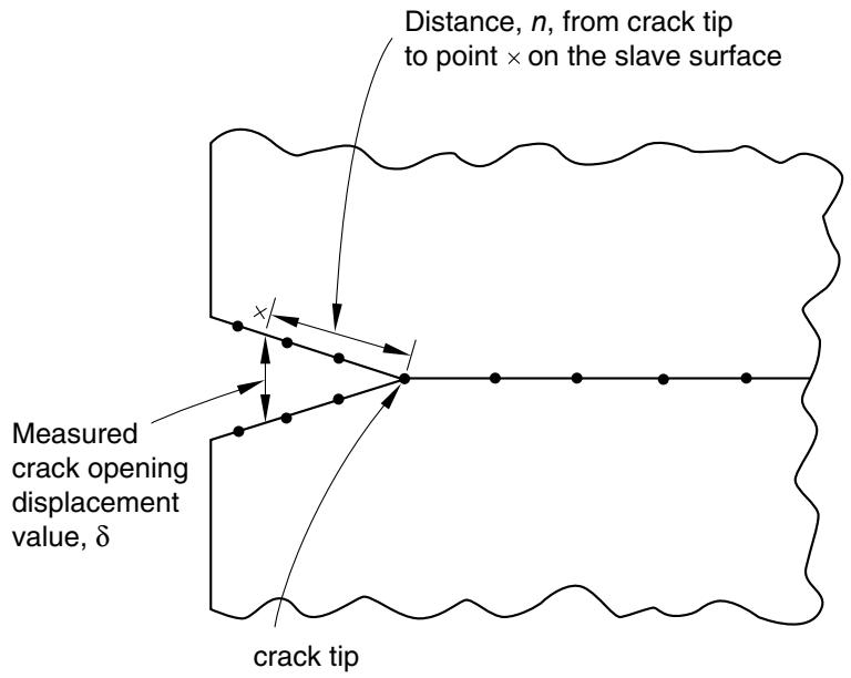
You specify the position, n, behind the crack tip where the critical crack opening displacement is calculated. The value of this position must be specified as the length of the straight line joining the current crack tip and points on the slave and master surfaces (Figure 11.4.3–2).
Abaqus/Standard computes the crack opening displacement at that point by interpolating the values at the adjacent nodes. The interpolation depends on whether first-order or second-order elements are used to define the slave surface. An error message will be issued if the value of n is not within the end points of the contact pair.
Input File Usage: $\scriptstyle * \mathrm { F R A C T U R E ~ C R I T E R I O N } , \mathrm { T Y P E } = \mathrm { C O D } , \mathrm { D I S T A N C E } = n$
Abaqus/CAE Usage: The critical crack opening displacement criterion is not supported in Abaqus/CAE.
# Modeling symmetry
In problems where the debonding surfaces lie on a symmetry plane, you can specify that Abaqus/Standard should consider only half of the user-specified crack opening displacement values. In this case the initial bonding must be in the normal direction only (see “Bonding only in the normal direction” above).
text_image
Distance, n, from crack tip
to point × on the slave surface
Measured
crack opening
displacement
value, δ
crack tip
Figure 11.4.3–2 Distance specification for the critical crack opening displacement criterion.
Input File Usage: \*FRACTURE CRITERION, TYPE=COD, DISTANCE=n, SYMMETRY Abaqus/CAE Usage: Modeling symmetry is not supported in Abaqus/CAE.
# Crack length versus time criterion
This criterion is available only in Abaqus/Standard.
To specify the crack propagation explicitly as a function of total time, you must provide a crack length versus time relationship and a reference point from which the crack length is measured. This reference point is defined by specifying a node set. Abaqus/Standard finds the average of the current positions of the nodes in the set to define the reference point. During crack propagation the crack length is measured from this user-specified reference point along the slave surface in the deformed configuration. The time specified must be total time, not step time.
The fracture criterion, f, is stated in terms of the user-specified crack length and the length of the current crack tip. The length of the current crack tip from the reference point is measured as the sum of the straight line distance of the initial crack tip from the reference point and the distance between the initial crack tip and the current crack tip measured along the slave surface.
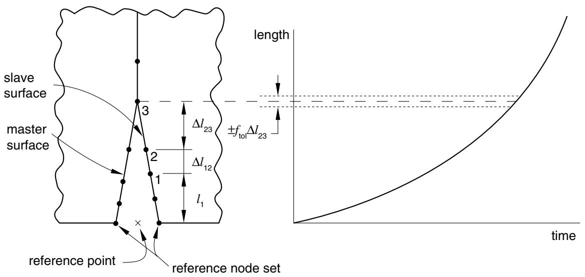
Referring to Figure 11.4.3–3, let node 1 be the initial location of the crack tip and node 3 be the current location of the crack tip. The distance of the current crack tip located at node 3 is given by
$$
l _ {3} = l _ {1} + \Delta l _ {1 2} + \Delta l _ {2 3},
$$
where $l _ { 1 }$ is the length of the straight line joining node 1 and the reference point, $\Delta l _ { 1 2 }$ is the distance between nodes 1 and 2, and $\Delta l _ { 2 3 }$ is the distance between nodes 2 and 3 measured along the slave surface.
text_image
slave
surface
master
surface
3
Δl₂₃
±fₜₒₗΔl₂₃
2
Δl₁₂
1
l₁
reference point
reference node set
length
time
Figure 11.4.3–3 Crack propagation as a function of time.
The fracture criterion, f, is given by
$$
f = \frac {l - (l _ {3} - \Delta l _ {2 3})}{\Delta l _ {2 3}},
$$
where l is the length at the current time obtained from the user-specified crack length versus time curve. Crack-tip node 3 will debond when the failure function f reaches the value of 1.0 (within the user-defined tolerance).
If geometric nonlinearity is considered in the step (“Defining an analysis,” Section 6.1.2), the reference point may move as the body deforms; you must ensure that this movement does not invalidate the crack length versus time criterion.
Abaqus/Standard does not extrapolate beyond the end points of your crack data. Therefore, if the first crack length specified is greater than the distance from the crack reference point to the first bonded node, the first bonded node will never debond and the crack will not propagate. In this case Abaqus/Standard will print warning messages in the message (.msg) file.
Input File Usage: \*FRACTURE CRITERION, TYPE=CRACK LENGTH, NSET=name
Abaqus/CAE Usage: The crack length versus time criterion is not supported in Abaqus/CAE.
# VCCT criterion
This criterion is available in both Abaqus/Standard and Abaqus/Explicit.