text_image
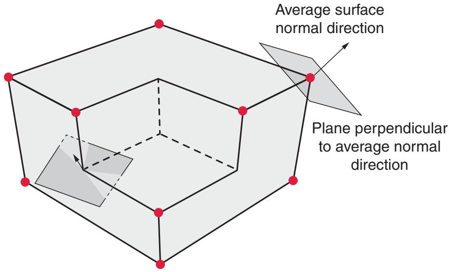
Average surface normal direction
Plane perpendicular to average normal direction
Figure 36.2.2–4 Examples of average surface normal directions and corresponding planes associated with vertex node criterion.
• If the average edge direction is zero, the node is not a vertex node; otherwise, the node is considered a vertex node if each feature edge connected to the node forms an angle greater than or equal to the vertex angle threshold with this plane, by default.
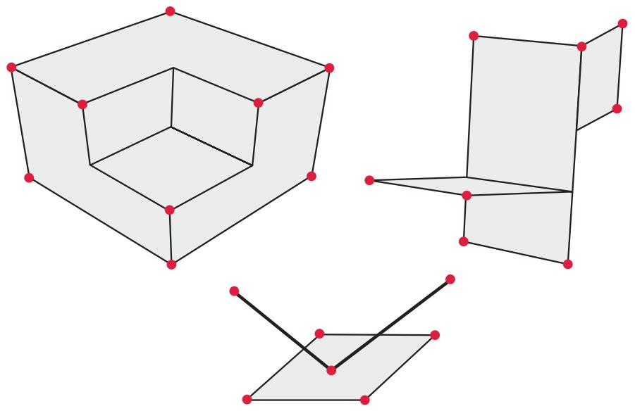
The default vertex angle threshold is 20°. The circular dots in Figure 36.2.2–5 represent examples of nodal locations that would satisfy one of the vertex node criteria, with the default vertex angle threshold in effect.
# Specifying a vertex angle threshold
You can control the vertex criteria globally or locally.
Input File Usage:
\*SURFACE PROPERTY ASSIGNMENT, PROPERTY=VERTEXCRITERIA
surface, vertex\_angle\_threshold
If the surface name is omitted, a default surface that encompasses the entire general contact domain is assumed.
# Specifying that vertex nodes should not be included
You can specify that no vertex nodes should be considered by the vertex-to-surface formulation globally or in a local region. However, doing so does not deactivate “contact edges” associated with beam and truss elements.
natural_image
Three geometric 3D wireframe structures with red dots and black lines, no text or symbols present
Figure 36.2.2–5 Examples of vertex locations represented by circular dots.
# Input File Usage:
\*SURFACE PROPERTY ASSIGNMENT, PROPERTY=VERTEXCRITERIA
surface, NO VERTICES
If the surface name is omitted, a default surface that encompasses the entire general contact domain is assumed.
# 36.2.3 CONTACT PROPERTIES FOR GENERAL CONTACT IN Abaqus/Standard
Products: Abaqus/Standard Abaqus/CAE
# References
• “Defining general contact interactions in Abaqus/Standard,” Section 36.2.1
• “Mechanical contact properties: overview,” Section 37.1.1
• “Contact pressure-overclosure relationships,” Section 37.1.2
• “Contact damping,” Section 37.1.3
• “Frictional behavior,” Section 37.1.5
• \*CONTACT
• \*CONTACT PROPERTY ASSIGNMENT
• \*SURFACE INTERACTION
• “Specifying and modifying contact property assignments for general contact,” Section 15.13.2 of the Abaqus/CAE User’s Guide, in the HTML version of this guide
# Overview
Contact properties:
• define the surface interaction models that govern the behavior of surfaces when they are in contact; and
• can be applied selectively to particular regions within a general contact domain.
# Assigning contact properties
The default contact property model in Abaqus/Standard assumes “hard” contact in the normal direction, no friction, no thermal interactions, etc. You can assign a nondefault contact property definition (surface interaction) to specified regions of the general contact domain.
Contact properties for general contact in Abaqus/Standard are assigned at the beginning of the analysis and cannot be modified across steps, with an exception for changes to the friction model, as discussed below.
The surface names used to specify the regions where nondefault contact properties should be assigned do not have to correspond to the surface names used to specify the general contact domain. In many cases the contact interaction will be defined for a large domain, while nondefault contact properties will be assigned to a subset of this domain. Any contact property assignments for regions that fall outside of the general contact domain will be ignored. The last assignment will take precedence if the specified regions overlap.
Input File Usage: \*CONTACT PROPERTY ASSIGNMENT
surface\_1, surface\_2, interaction\_property\_name
This option must be used in conjunction with the \*CONTACT option and should appear at most once; the data line can be repeated as often as necessary to assign contact properties to different regions.
If the first surface name is omitted, a default surface that encompasses the entire general contact domain is assumed. If the second surface name is omitted or is the same as the first surface name, contact between the first surface and itself is assumed. Surfaces can be defined to span multiple unattached bodies, so self-contact is not limited to contact of a single body with itself. If the interaction property name is omitted, the unnamed set of default contact properties in Abaqus/Standard is assumed. If an interaction property name is specified, it must also appear as the value of the NAME parameter on a \*SURFACE INTERACTION option in the model portion of the input file.
# Abaqus/CAE Usage:
Use the following options to assign a global contact property to the entire general contact domain:
Interaction module: Create Interaction: General contact (Standard): Contact Properties: Global property assignment:
interaction\_property\_name
Use the following options to assign contact properties to individual surface pairs:
Interaction module: Create Interaction: General contact (Standard): Contact Properties: Individual property assignments: Edit: select the surfaces and the contact property in the columns on the left, and click the arrows in the middle to transfer them to the list of contact property assignments
In Abaqus/CAE you must assign a global contact property; Abaqus/CAE does not assume a default contact interaction property. Contact properties assigned to individual surface pairs override the global assignment.
# Changing friction properties during an analysis
The friction properties associated with a given named surface interaction definition can be modified in any particular step of an Abaqus/Standard analysis, as discussed in “Changing friction properties during an Abaqus/Standard analysis” in “Frictional behavior,” Section 37.1.5.
# Example
The following contact property assignments are specified below as model data in a general contact analysis:
• a global assignment of contProp1 to the entire general contact domain;
• a local assignment of contProp2 to self-contact for surf1;
• a local assignment of the default Abaqus contact property to contact between surf2 and surf3; and
• a local assignment of contProp3 to contact between the entire contact domain and surf4. The friction coefficient for contProp3 is reset from the initial value of 0.20 to 0.05 in the second step.
```txt
*SURFACE INTERACTION, NAME=contProp1
*FRICTION
0.1
*SURFACE INTERACTION, NAME=contProp2
*FRICTION
0.15
*SURFACE INTERACTION, NAME=contProp3
*FRICTION
0.20
*CONTACT
*CONTACT INCLUSIONS, ALL EXTERIOR
*CONTACT PROPERTY ASSIGNMENT
, , contProp1
surf1, surf1, contProp2
surf2, surf3,
, surf4, contProp3
...
*STEP
Step1
*STATIC
...
*END STEP
*STEP
Step2
*STATIC
...
*CHANGE FRICTION, INTERACTION NAME=contProp3
*FRICTION
0.05
*END STEP
```
# 36.2.4 CONTROLLING INITIAL CONTACT STATUS IN Abaqus/Standard
Products: Abaqus/Standard Abaqus/CAE
# References
• “Defining general contact interactions in Abaqus/Standard,” Section 36.2.1
• \*CONTACT INITIALIZATION ASSIGNMENT
• \*CONTACT INITIALIZATION DATA
• “Creating contact initializations,” Section 15.12.4 of the Abaqus/CAE User’s Guide, in the HTML version of this guide
• “Specifying and modifying contact initialization assignments for general contact,” Section 15.13.3 of the Abaqus/CAE User’s Guide, in the HTML version of this guide
# Overview
Contact initialization controls for general contact in Abaqus/Standard:
• can be used to specify whether initial overclosures should be resolved without generating stresses and strains or treated as interference fits that are gradually resolved over multiple increments; and
• can be used to specify nondefault search zones that determine which nodes are affected in the case of strain-free adjustments or interference fits.
Abaqus/Standard initializes the contact state based on the gap or penetration state observed in the initial geometry. Small initial contact overclosures are resolved by default using strain-free adjustments to the positions of surface nodes. You can define alternative contact initialization methods and then assign them to contact interactions. For example, you can choose to have initial overclosures for certain interactions treated as interference fits.
# Default contact initialization method
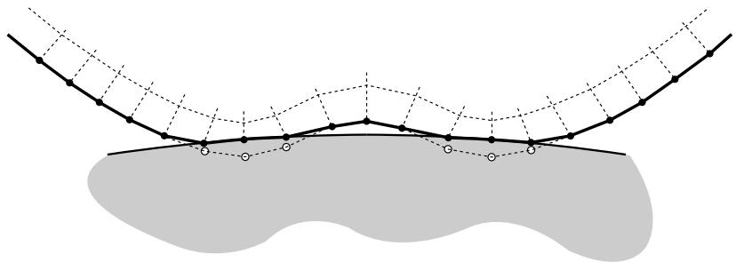
By default, the general contact algorithm adjusts the initial positions of surface nodes during preprocessing to remove small initial surface overclosures without generating strains or stresses in the model, as shown in Figure 36.2.4–1. These adjustments are intended to correct only minor mismatches associated with mesh generation.
General contact automatically assigns master and slave roles for contact interactions, as discussed in “Numerical controls for general contact in Abaqus/Standard,” Section 36.2.6. Abaqus/Standard calculates an overclosure tolerance based on the size of the underlying element facets on a slave surface. Slave surfaces in a particular interaction are repositioned onto the associated master surface (using strain-free adjustments) if the two surfaces are initially overclosed by a distance smaller than the calculated tolerance. Initial gaps between surfaces remain unchanged by default adjustments. If a portion of a slave surface is initially overclosed by a distance greater than the calculated tolerance, Abaqus/Standard automatically generates a contact exclusion for this surface portion and its associated
natural_image
Abstract diagram with curved lines and shaded regions, no text or symbols present
Figure 36.2.4–1 Configuration of contact surfaces after strain-free adjustments to resolve overclosure.
master surface. Therefore, general contact does not create interactions between surfaces (or portions of surfaces) that are severely overclosed in the initial configuration of the model, and these surfaces can freely penetrate each other throughout the analysis.
General contact uses the finite-sliding, surface-to-surface contact formulation, so penetration/gap calculations are computed as averages over finite regions; therefore, it is possible for penetrations and gaps to be present at individual surface nodes after the adjustments. The default adjustments will not resolve initial crossings of two reference surfaces associated with shells or membranes, although techniques to resolve such cases are discussed in “Assigning contact initializations to shell surfaces.”
# Defining alternative contact initialization methods
You can define alternative contact initialization methods if the default behavior is not desired. For example, you may want to increase the tolerance for deep penetrations or specify that certain openings should be adjusted to a “just touching” status. Furthermore, some analyses call for initial overclosures to be treated as interference fits rather than resolved with strain-free adjustments. To modify the contact initialization behavior, you must define one or more alternate contact initialization methods and then identify which surface pairings are to use which methods.
You assign a name to each contact initialization method. This name is used in the assignment of a contact initialization method to specific surface pairings (see “Assigning contact initialization methods” below).
Input File Usage: \*CONTACT INITIALIZATION DATA, NAME=contact\_initialization\_method\_name
Abaqus/CAE Usage: Interaction module: Interaction→Contact Initialization→Create: Name: contact\_initialization\_method\_name
# Increasing the search zones for strain-free adjustments
As discussed above in “Default contact initialization method,” initial gaps and large initial overclosures between surfaces are not adjusted by the default contact initialization methods. You can optionally specify nondefault search distances both above and below the surfaces in an interaction; slave surfaces that lie within these search distances are repositioned directly onto their associated master surface using
strain-free nodal adjustments. Abaqus/Standard takes shell thickness into account when calculating these search distances.
Specifying a search distance above a surface is used to close small initial gaps between surfaces. Specifying a search distance below a surface is used to increase the default overclosure tolerance that Abaqus/Standard uses when performing strain-free adjustments; if you specify a search distance smaller than the default overclosure tolerance, Abaqus/Standard uses the default tolerance instead. As with the default initialization behavior, contact exclusions are created for initial overclosures that are larger than the specified search zone.
Increasing the extent of the search zones for strain-free adjustments can potentially increase the computational cost of an analysis. It is not generally recommended that you specify a large search zone since this may cause mesh distortion when nodes are repositioned over large distances.
Input File Usage: \*CONTACT INITIALIZATION DATA, SEARCH ABOVE=a, SEARCH BELOW=b
Abaqus/CAE Usage: Interaction module: Interaction→Contact Initialization→Create: Resolve with strain-free adjustments: Ignore overclosures greater than: b, Ignore initial openings greater than: a
# Specifying an initial clearance distance
By default, the strain-free adjustments discussed above will adjust initial nodal positions such that surfaces are “just-touching” (with zero penetration/separation). Alternatively, Abaqus/Standard can make the adjustments to achieve an initial clearance distance that you specify. The adjustments will occur only for regions that satisfy the search zone tolerances, as discussed above. Mesh distortion can occur if large strain-free adjustments are necessary to achieve the specified initial clearance distance.
Input File Usage: \*CONTACT INITIALIZATION DATA, INITIAL CLEARANCE=h
Abaqus/CAE Usage: Interaction module: Interaction→Contact Initialization→Create: Specify clearance distance: h
# Modeling interference fits
Optionally, the general contact algorithm in Abaqus/Standard can treat initial overclosures as interference fits. The general contact algorithm uses a shrink-fit method to gradually resolve the interference distance over the first step of the analysis (if multiple load increments are used for the first step) as shown in Figure 36.2.4–2, such that the fraction of the interference resolved up to and including a particular increment approximately corresponds to the fraction of the step completed. Stresses and strains are generated as the interference is resolved. Gradually resolving interference over several increments improves robustness (compared to always resolving the full interference in the first increment, which is the default for contact pairs) for cases in which a nonlinear response occurs for “interference-fit loading.” It is generally recommended that you do not apply other loads while the interference fit is being resolved.
Because contact conditions are enforced in an average sense in a region around each constraint location for the surface-to-surface contact formulation used by general contact in Abaqus/Standard,
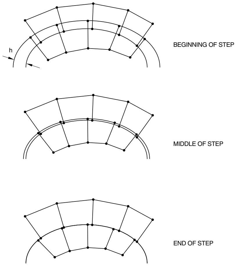
BEGINNING OF STEP
MIDDLE OF STEP
END OF STEP
Figure 36.2.4–2 Gradual resolution of contact interference fit.
penetrations or gaps may be observed at slave nodes when surface-to-surface constraints are in a zero-penetration state.
Input File Usage: \*CONTACT INITIALIZATION DATA, INTERFERENCE FIT
Abaqus/CAE Usage: Interaction module: Interaction→Contact Initialization→Create: Treat as interference fits
Increasing the tolerance for interference fits
Abaqus/Standard calculates an overclosure tolerance based on the size of the underlying element facets on a slave surface (see “Default contact initialization method” above). An interference fit between two surfaces affects only those slave surfaces that are overclosed by a distance smaller than the calculated tolerance; contact is ignored entirely for surfaces that are overclosed by a distance greater than the calculated tolerance.