# Applying smoothing of common curved surface geometries to surface-to-surface contact pairs
Smoothing of common curved surface geometries for contact pairs that use a surface-to-surface contact formulation is enabled by creating a surface smoothing definition. A contact pair definition references this smoothing definition to apply geometric corrections in the contact formulation (the physical geometry of the model is not altered).
The surface smoothing definition lists all of the faceted regions in the contact pair surfaces that must be smoothed, as well as the geometry correction method that should be applied to each region. Three geometry correction methods can be employed:
• The circumferential smoothing method is applicable to surfaces approximating a portion of a circle in two dimensions or a portion of a surface of revolution in three dimensions.
• The spherical smoothing method is applicable to surfaces approximating a portion of a sphere in three dimensions.
• The toroidal smoothing method is applicable to surfaces approximating a portion of a torus in three dimensions (i.e., a circular arc revolved about an axis).
Each surface-to-surface contact pair refers to a single smoothing definition; therefore, a smoothing definition must list all of the smoothed regions and applicable geometry correction methods for the contact pair. Geometry corrections can be applied to master surfaces and to slave surfaces; you can also apply corrections to selected regions of each surface. A surface smoothing definition can include multiple regions and different geometric correction methods for each region. For each region, you must specify the appropriate geometry correction method and either the approximate axis of revolution (for circumferential or toroidal smoothing) or the approximate spherical center (for spherical smoothing). For toroidal smoothing, you must also specify the distance of the center of the circular arc from the axis of revolution, and the line joining point $\left( { { { \mathrm { X } } _ { \mathrm { a } } } , \ { { \mathrm { Y } } _ { \mathrm { a } } } , { Z _ { \mathrm { a } } } } \right)$ and the center of the circular arc should be perpendicular to the axis of revolution.
# Input File Usage:
Use both of the following options to apply surface-to-surface contact smoothing:
```sql
*CONTACT PAIR, GEOMETRIC CORRECTION=smoothing_name
*SURFACE SMOOTHING, NAME=smoothing_name
data lines to define smoothing regions (see below)
```
Use the following data line to apply circumferential smoothing to surface regions with an axis of symmetry passing through points $(X_{a}, Y_{a}, Z_{a})$ and $(X_{b}, Y_{b}, Z_{b})$ :
slave_region, master_region, CIRCUMFERENTIAL, $X_{a}$ , $Y_{a}$ , $Z_{a}$ , $X_{b}$ , $Y_{b}$ , $Z_{b}$
Use the following data line to apply spherical smoothing to surface regions with a spherical center at point $(X_{a}, Y_{a}, Z_{a})$ : slave_region, master_region, SPHERICAL, $X_{a}, Y_{a}, Z_{a}$
Use the following data line to apply toroidal smoothing to
surface regions with an axis of symmetry passing through points
$( \mathrm { X } _ { \mathrm { a } } , \mathrm { Y } _ { \mathrm { a } } , \mathrm { Z } _ { \mathrm { a } } )$ and $( X _ { \mathrm { b } } , \ : \mathrm { Y _ { \mathrm { b } } , Z _ { \mathrm { b } } ) }$ with the center of the revolved circular arc at a distance R from the axis of symmetry:
$s l a \nu e \_ r e g i o n , m a s t e r \_ r e g i o n , \mathrm { T O R O I D A L } , X _ { a } , Y _ { a } , Z _ { a } , X _ { b } , Y _ { b } , Z _ { b } , R$
Repeat the data lines as many times as necessary to define the appropriate geometry corrections for all surfaces in the contact pair.
# Abaqus/CAE Usage:
Abaqus/CAE can automatically identify any circumferential, spherical, or toroidal surfaces in a contact interaction that will benefit from contact smoothing and apply the necessary geometry correction methods.
Interaction module: contact interaction editor: Surface Smoothing:
# Automatically smooth 3D geometry surfaces when applicable
Surface-to-surface contact smoothing cannot be applied to surfaces on orphan mesh models.
# Example: Pin-in-hole with contact pairs
To improve contact pressure accuracy for the model in Figure 38.1.3–1, contact smoothing can be applied to both the master and slave surfaces. Two different geometric correction methods are required for the pin (the slave surface), so additional surfaces are defined corresponding to regions of the slave surface. Spherical smoothing is defined for the tip of the pin. Since the body of the pin and the hole share an axis of revolution, circumferential smoothing is applied to both of these surfaces. This surface smoothing definition applies even if the cross-sectional shapes of the pin and hole deviate from perfect circles.
*CONTACT PAIR, TYPE=SURFACE TO SURFACE, INTERACTION=FRICTION1, GEOMETRIC CORRECTION=SMOOTH1
PIN, HOLE
*SURFACE INTERACTION, NAME=FRICTION1
*SURFACE SMOOTHING, NAME=SMOOTH1
PIN_TIP, SPHERICAL, $X_{b}$ , $Y_{b}$ , $Z_{b}$ PIN_BODY, HOLE, CIRCUMFERENTIAL, $X_{a}$ , $Y_{a}$ , $Z_{a}$ , $X_{b}$ , $Y_{b}$ , $Z_{b}$
# Smoothing of faceted surfaces based on comparison to CAD representations
Simulations using general contact submitted from 3DEXPERIENCE platform Scenario Creation apps can use a technique to improve finite element representations of contact surfaces. This technique is based on deviations of the original element-based surface geometry from a more accurate reference representation of the undeformed geometry and leverages CAD surface representations available in the 3DEXPERIENCE platform in the computation of contact geometry corrections. This technique is not available in explicit dynamic steps.
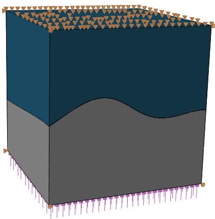
The CAD-based smoothing method is applicable to arbitrary surface shapes having CAD representations in the 3DEXPERIENCE platform. Consider the example shown in Figure 38.1.3–3. This example is constructed such that the analytical solution has a uniform, uniaxial stress state of
108 Pa. The curved contact interface has closed contact and sticking friction everywhere, and the same elastic material exists on both sides of the contact interface. The meshes used in this example are made of quadratic hexahedral and wedge elements. The meshes do not have matched nodes across the contact interface, which causes significant stress noise if the contact surfaces are not smoothed, especially for small strains where the level of element deformation is less than or equal to the distances associated with the mismatch of faceted surface representations across the interface.
natural_image
3D diagram of a layered structure with purple and gray components and triangular elements at the top (no text or symbols)
Figure 38.1.3–3 Two solid blocks contacting on an arbitrarily curved interface (subjected to uniform unidirectional compressive stress).
Figure 38.1.3–4 shows that CAD-enhanced contact reduces stress noise for this example. For example, the maximum Mises stress deviates from the analytical Mises stress solution by 33% without CAD-enhanced contact, and this deviation is less than 3% with CAD-enhanced contact. The CAD-based smoothing also significantly improves contact pressure results for this model.
# Considerations for smoothing methods based on knowledge of idealized initial geometry
The smoothing methods in this section are used to adjust contact penetration/gap computations based on differences in undeformed geometries between faceted finite element surface representations and more idealized surface representations. The effects of the surface smoothing techniques discussed in this section tend to be most significant for analyses involving small deformation and coarse mesh discretization with first-order elements in the contact region; however, significant improvements to contact stress solutions are common even when the mesh is quite refined or higher-order elements are used. For analyses with large deformation these smoothing techniques typically have an insignificant effect on solutions. However, in some cases the smoothing can degrade the solution accuracy after large deformation; therefore, it is not recommended to use these smoothing techniques for large-deformation analyses. The effectiveness of the smoothing does not degrade upon relative motion between contact
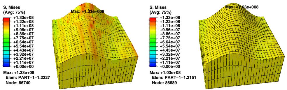
Figure 38.1.3–4 Comparison of the Mises stress field between the case without geometry-based corrections (left) and with geometry-based corrections applied to the curved contacting surfaces (right).
surfaces; for example, the smoothing technique works well for cases involving large sliding but small deformation.
The surface smoothing techniques discussed in this section assume that initial locations of surface nodes lie on the true initial surface geometry, with the exception of midside nodes of higher-order elements. These smoothing techniques remain effective even if the midside nodes of higher-order elements do not lie on the true initial geometry (models meshed using Abaqus/CAE always have midside nodes placed on the true initial geometry, but this may not be the case with other meshing preprocessors).
# 38.2 Contact formulations and numerical methods in Abaqus/Explicit
• “Contact formulation for general contact in Abaqus/Explicit,” Section 38.2.1
• “Contact formulations for contact pairs in Abaqus/Explicit,” Section 38.2.2
• “Contact constraint enforcement methods in Abaqus/Explicit,” Section 38.2.3
# 38.2.1 CONTACT FORMULATION FOR GENERAL CONTACT IN Abaqus/Explicit
Products: Abaqus/Explicit Abaqus/CAE
# References
• “Defining general contact interactions in Abaqus/Explicit,” Section 36.4.1
• \*CONTACT
• \*CONTACT FORMULATION
• “Specifying master-slave assignments for general contact,” Section 15.13.6 of the Abaqus/CAE User’s Guide, in the HTML version of this guide
# Overview
The contact formulation used with the general contact algorithm in Abaqus/Explicit:
• includes the contact surface weighting, surface polarity, and the sliding formulation; and
• can be applied selectively to particular regions within a general contact domain.
The general contact formulation uses a penalty method to enforce contact constraints between surfaces; the constraint enforcement method is discussed in “Contact constraint enforcement methods in Abaqus/Explicit,” Section 38.2.3.
# Specifying the contact formulation
Currently you can specify only the contact surface weighting and polarity for the general contact algorithm. The contact formulation propagates through all analysis steps in which the general contact interaction is active.
The surface names used to specify the regions where a nondefault contact formulation should be assigned do not have to correspond to the surface names used to specify the general contact domain. In many cases the contact interaction will be defined for a large domain, while a nondefault contact formulation will be assigned to a subset of this domain. Any contact formulation assignments for regions that fall outside the general contact domain will be ignored. The last assignment will take precedence if the specified regions overlap.
Input File Usage: \*CONTACT FORMULATION
This option must be used in conjunction with the \*CONTACT option. It should appear at most once per step for each value of the TYPE parameter; the data line can be repeated as often as necessary to assign contact formulations to different regions.
Abaqus/CAE Usage: Interaction module: Create Interaction: General contact (Explicit): Contact Formulation
# Contact surface weighting
Generally, contact constraints in a finite element model are applied in a discrete manner, meaning that for hard contact a node on one surface is constrained to not penetrate the other surface. In pure master-slave contact the node with the constraint is part of the slave surface and the surface with which it interacts is called the master surface. For balanced master-slave contact Abaqus/Explicit calculates the contact constraints twice for each set of surfaces in contact, in the form of penalty forces: once with the first surface acting as the master surface and once with the second surface acting as the master surface. The weighted average of the two corrections (or forces) is applied to the contact interaction.
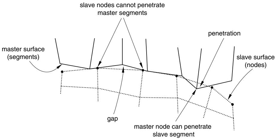
Balanced master-slave contact minimizes the penetration of the contacting bodies and, thus, provides better enforcement of contact constraints and more accurate results in most cases. In pure master-slave contact the nodes on the master surface can, in principle, penetrate the slave surface unhindered (see Figure 38.2.1–1).
flowchart
```mermaid
graph TD
A["master surface (segments)"] --> B["slave nodes cannot penetrate master segments"]
B --> C["penetration"]
C --> D["slave surface (nodes)"]
D --> E["master node can penetrate slave segment"]
E --> F["gap"]
F --> A
```
Figure 38.2.1–1 Master surface penetrations into the slave surface in pure master-slave contact due to coarse discretization.
The general contact algorithm in Abaqus/Explicit uses balanced master-slave weighting whenever possible; pure master-slave weighting is used for contact interactions involving node-based surfaces, which can act only as pure slave surfaces and for contact interactions involving analytical rigid surfaces, which can act only as pure master surfaces. Surface-based cohesive behavior also always uses a pure master-slave algorithm. However, you can choose to specify a pure master-slave weighting for other interactions as well.
There is no master-slave relationship for edge-to-edge contact; both contacting edges are given equal weighting.
# Specifying pure master-slave weighting for node-to-face contact
You can specify that a general contact interaction should use pure master-slave weighting for node-toface contact. This specification has no effect on edge-to-edge contact and cannot be used to make a node-based surface act as a master surface. When two originally flat surfaces contact one another, a more uniform penetration distance distribution (and consequently pressure distribution) may result with pure master-slave weighting where the more refined surface acts as the slave surface as compared to balanced master-slave weighting. This can be particularly evident if the mesh densities of the contacting surfaces differ significantly—with balanced weighting the contact penetrations will be smaller near the nodes of the coarsely meshed surface.
Abaqus/Explicit will automatically generate contact exclusions for the master-slave orientation opposite to that specified; therefore, node-to-face self-contact will be excluded for any regions of the two surfaces that overlap. For example, specifying that the general contact interaction between surf\_A and surf\_B should use pure master-slave weighting with surf\_A considered to be the slave surface would result in exclusions being generated internally for faces of surf\_A contacting nodes of surf\_B; node-to-face self-contact would be excluded for the region of overlap between surf\_A and surf\_B. A warning message will be issued if the second surface name is omitted or is the same as the first surface name since this input would result in the exclusion of node–face self-contact for the surface.
Input File Usage: Use the following option to indicate that the first surface should be considered the slave surface (default):
\*CONTACT FORMULATION, TYPE=PURE MASTER-SLAVE surf\_1, surf\_2, SLAVE
Use the following option to indicate that the first surface should be considered the master surface:
\*CONTACT FORMULATION, TYPE=PURE MASTER-SLAVE surf\_1, surf\_2, MASTER
If the first surface name is omitted, a default surface that encompasses the entire general contact domain is assumed. The second surface name must be specified.
Abaqus/CAE Usage: Interaction module: Create Interaction: General contact (Explicit): Contact Formulation: Pure master-slave assignments: Edit: select the surfaces in the columns on the left, and click the arrows in the middle to transfer them to the list of master-slave assignments.
In the First Surface Type column, enter SLAVE to indicate that the first surface should be considered the slave surface, and enter MASTER to indicate that the first surface should be considered the master surface.
# Contact surface polarity
By default, general contact considers both sides of all double-sided elements in surfaces specified to be included for contact purposes (side labels of double-sided elements are ignored). This default can be
overridden for node-to-face and Eulerian-Lagrangian contact and in some cases results in more accurate enforcement of contact.
Surface polarity is not considered for edge-to-edge contact, including edges activated on faces of solid elements.
# Specifying surface polarity for node-to-face and Eulerian-Lagrangian contact
Changing the polarity of double-sided elements forces the contact algorithm to treat them as if they were solid elements. More accuracy may be gained by converting double-sided elements to single-sided if there is a chance that slave nodes may be “caught” behind the surface in node-to-face contact or if material contained on one side of a double-sided surface leaks to the other side in Eulerian-Lagrangian contact. Improvements in performance and memory use may also be observed with Eulerian-Lagrangian contact if double-sided Lagrangian surfaces are converted to single-sided for contact with all Eulerian material surfaces.
# Input File Usage:
Use the following option to indicate that the sides of the (double-sided) elements specified in the second surface’s definition should be considered for contact with the first surface:
\*CONTACT FORMULATION, TYPE=POLARITY surf\_1, surf\_2
Use the following option to indicate that the SPOS side of the (double-sided) elements in the second surface should be considered for contact with the first surface:
\*CONTACT FORMULATION, TYPE=POLARITY surf\_1, surf\_2, SPOS
Use the following option to indicate that the SNEG side of the (double-sided) elements in the second surface should be considered for contact with the first surface:
\*CONTACT FORMULATION, TYPE=POLARITY surf\_1, surf\_2, SNEG
Use the following option to indicate that both sides of the (double-sided) elements in the second surface should be considered for contact with the first surface:
\*CONTACT FORMULATION, TYPE=POLARITY surf\_1, surf\_2, TWO SIDED
If the first surface name is omitted, a default surface that encompasses the entire general contact domain is assumed. The second surface name must be specified.
# Sliding formulation
Currently only the finite-sliding formulation is available for general contact in Abaqus/Explicit. This formulation allows for arbitrary separation, sliding, and rotation of the surfaces in contact. For cases in